Diagonal Thrust
Now here also the aetherpoints aside each other are some later at their tracks, i.e. the three columns as a whole are ´time-shifted´. From left towards right come up following situations. Here e.g. at left border the blue arrow A marks how that edge seemingly ´slides´ upward. Also at the right edge is marked by arrow B, how that ´wave´ is moving upward (watching the columns from left to right). Really existing are only motions at pure circled tracks at the diverse levels. But still the follow of time-shifted movements appears like a diagonal upward directed thrust. Each magnetic fieldline affects a ´spiral-turning flow´ from north- to south-pole.
Right side at the picture at D schematic is drawn a cross-sectional view through the conductor. Around the wire (grey) the current is running within a thin ring-shaped layer (red). Outside of the current-by-itself, the magnetic field (light-green) reaches far out into the space all around. By view on the minus-end of the wire, the magnetic field is left-turning (see red arrows).
Current through Magnetic Field
At right side previous edge A is drawn, which there is ´screwing upward´. This side shows relative few problems, because both movements are upward directed (see blue arrow A and red arrow F). At left side, previous edge B interacts with the light-green magnet-field. This side is problematical, because there the downward-movement around the conductor (red arrow F) is opposite to the upward-movement of the fieldline (blue arrow B). There the magnetic field around the conductor is affected by a counter-pressure (G, black arrow).
Also a pure mechanical comparison shows the problem clearly. Both magnetic fieldlines work like thread-rods (blue), both left-turning around vertical axis, like sketched at this picture below at left and right side. The magnetic field of the current then is comparable with a gear-wheel (H, light-green) with horizontal axis. The gear-teeth are build diagonal, so the right thread-rod produces the necessary left-turning of the current-gear-wheel. This interlocking however does not fit to the necessary motions at left side. There would come up ´transmission-trouble´ respective here within the aether comes up stress.
Swerve aside
Opposite, the magnetic field around the conductor is easier to move, because it´s anyway shifted forward along the wire. The counter-pressure A thus is affected by less resistance, when the green magnetic field is compressed little bit, like marked by arrow B. This field now is no longer concentric to the wire, thus inside of comes up tension. If the wire is movable, the wire is pushed towards right side, like marked by arrow C. This is the cause and the process, why current-carrying conductors within a homogenous magnetic field are affected by the ´Lorentz-Force´ as a sideward thrust.
At this picture right side, a rotor (R, yellow) is drawn by cross-sectional view. Upside at D is drawn a conductor, where current is running from foreground backward. The Lorentz-Force pushes that wire towards right. Below a E a conductor is drawn, where current flows into opposite direction. Its enclosing magnet field is right-turning by this view and the Lorentz-Force presses that wire towards left side. Both thrust-forces (see black arrows) result a turning momentum at the rotor. However that thrust is affecting only each half turns, like marked by arrows F.
DC-Motor
The change of current-direction is done by a ´commutator´ (K). It exists by two half-circles (marked green and red), each connected with the ends of previous wire (however isolated mutually and versus the shaft). Via slide-contact (e.g. in shape of carbon-brushes) the current is fed from a DC-source. Here the direct-current all times is guided to the conductor-section which momentary is positioned upside and guided back all times by the section momentary positioned below.
At textbooks for example it sounds like this: " A wire-loop within a magnet field is affected by a pair of Lorentz-Force and a mechanical turning momentum M = ... comes up. The turning moments adjusts the wire-loop that kind, the perpendicular-face is moved parallel to B. This is the basis for electric motors". Everybody knows that well and everybody has seen the simple model of an electromotor. However in reality are working only mini-motors by this principle, effective devices are based on other principles (see later chapters). Nevertheless that Lorentz-Force exists, which was and still remained ´wondrous´. Finally previous considerations, based on existence of a real aether with characteristics claimed here, prove a logic explanation of that electromagnetic ´wonder´.
Reversal Conclusion
At A the conductor is moving upward within the magnetic field. By common understanding, no interactions exist at this process. The aetherpoints simply are swinging at their levels and their circled tracks. They also penetrate the copper-material of the conductor. The aether around the conductor simply swings some to and fro, without building a turning layer around the wire.
No Current
The advancing of the conductor affects a pressure onto the magnetic fieldlines. There will come up vortices to reduce the tensions. However the induced vortices have no clear structure. These vortices can calm down, when afterwards the conductor is moving down at C, thus parallel to the fieldlines and thus without interaction.
At D the conductor crosses the fieldlines once more, in opposite direction. Now the counter-pressure (G, see arrows) come up at left side, forcing the aether right-turning around the conductor. A corresponding current would flow from the background forward. However at this edge the aether is pressing backward. So as a whole, this arrangement can not produce well structured current, but only temporary whirls.
Induced Voltage
Based on many ´classic´ experiments the ´law of electromagnetic induction´ was formulated. In the given case is stated: "If a coil is turned within a permanent magnetic field, one can observe the appearing and disappearing of an induced voltage, two times each revolution". So this voltmeter will deflect twice during one revolution of the rotor respective the conductor-loop within the magnetic field. This is ´valid law´ - even one does not know why and how that effect really occurs.
Asymmetries
As mentioned upside, the magnetic fieldlines at the surface of the north-pole are strong bound at their source. The internal twisting aether-movements must exit exactly at their locations, in shape of a spiral motion-pattern, into the environment, by their original shape. At this picture this fact is marked by thick blue arrows upside of the north-pole. If a ´disturbing foreign body´ is crossing near along that surface, strong whirls within the aether around the conductor will come up. This ´charge in shape of strong aether-vortices´ is marked by dark-green area at E.
At the surface of the south-pole less necessity exists by ´sucking-in´ of suitable motions. Like at whirlwinds, the ´suction-trunk´ can twist and wind around. In addition, the disturbances near the north-pole damaged the magnetic fieldlines, so near the south-pole they are no longer in their original precise shape. At this picture this fact is marked by smaller and curved blue arrows below the surface of the south-pole. If the conductor crosses that area of motions less ordered, at the surface of the wire will stick less vortices all around. This weaker ´charge´ of the conductor at the south-pole is marked by the light-green face.
Few Charge-Difference
At both sections of the conductor-loop these vortices-layers show different height. So the high charge-density (dark-green) is pressed towards the low charge-density (light-green). So along the wire (or the wires of a coil) at the rear end of the rotor, an exchange of charge occurs. At the front-side of the rotor (via the commutator) thus only the remaining rest of voltage is measured by the voltmeter.
So probably much higher voltage is generated within the conductor-loop than the voltmeter indicates. At the other hand, the distance between north- and south-poles is rather far at this construction. In addition the magnetic field is too in-homogenous for generating a well ordered motion-pattern. That´s why this conception is not really effective and merely used for production of voltage.
Charge-Catcher
Clear might be the fact, the charge is generated only at these sections of a conductor-loop, which momentary are crossing the face of a pole (preferably a north-pole). Charge however needs no closed circuit. For example, charge can (temporary) be stored also at the surface of a metallic-sphere or a capacitor-sheet, where only one wire is necessary. So the connection between both sections is not necessary. That part of the loop is even damaging because it allows an exchange of voltage without useful effect.
The logic consequences are sketched at this picture upside right at B. The part below of the loop is cut off. Only the remaining two tips of wire now reach into the magnetic field (light-blue) between north- and south-pole. These constructional elements should be build as stabile metallic bolts or thin tubes. I call these new elements the ´charge-catcher´ LF. Like previous loop now both bolts are turning within the magnetic field. If momentary a bolt crosses the north-pole, it will get covered with high charge (dark-green). The other bolt same time crosses the south-pole and will catch less charge (light-green).
If both bolts are connected with a voltmeter, it will indicate voltage. Because no longer exists an exchange between both bolts, the voltage will be stronger than at the ´classic´ wire-loop (at previous A). Quite upside right a voltmeter is installed between right bolt and the earth E. In comparison with the ´normal-charge´ of the earth, the voltmeter will show some voltage, because the right bolt did catch some charge by crossing the (somehow disturbed and weakened) magnetic field of south-pole. The whole strength of generated charge however indicates a voltmeter between the left charge-catcher (dark-green) and the earth.
Charge-Generator
At the rotor-shaft (R, yellow) two horseshoe-magnets are installed (at this example). The north-pole (N, light-blue) is positioned inside, the south-pole (S, red) some outside of. The magnet are fed by a coil, which is served with DC (by common techniques, here not drawn). This current is running all times into same direction. Within the iron-core of the magnet occurs no reversal of polarity. So practically results a permanent magnetization. The strength of the magnetic field between the poles is intensified only by short current-impulses.
The rotor of this example is build only by a cross-beam with these two magnets. Naturally several magnet-beams could be installed. However between the magnets should exist sufficient distance. The yellow face left side at the cross-sectional view thus is no rotor-disk but marks only the turning-area of the magnet-beam.
The charge-catcher (LF, green) are reaching from left side (at this picture) into the space between north- and south-pole. Here as an example are drawn each five bolts at four units. During the rotation, the magnetic fields are crossing the stationary charge-catchers. The distance of the faces between north- and south-pole is small. So strong whirls are achieved at the surfaces of the charge-catchers.
Current-Flow by Aether-Pressure
The charge exists by aether-vortices more or less ordered around the surface of these bolts. Against that ´wide-range motion-mess´ stands the narrow trembling of Free Aether. The resulting aether-pressure ´wants to eliminate that disturbance´. It presses down the vortices at the conductor, until a balance of charge-density is achieved. There the law ´in-drive-direction-left´ is valid. The initially unordered vortices are transformed into a ordered left-turning magnetic field around the conductor, which thereby becomes current-carrying.
At previous longitudinal cross-sectional view is sketched only schematic, how the generated direct-current is guided to a consumer (V, blue) and finally is running into the earth (E). When ever a magnetic field crosses a group of charge-catchers, a current-impulse comes up. The pulsating currents can be transferred into useable shapes by known technology, e.g. also in alternating current. Naturally the number of magnets and (groups of) charge-catchers can be arranged within that machines as one likes it, e.g. for generating three-phase-current.
Fluid-conform Shapes
Upside left at A is drawn an alternative arrangement. Around the shaft of rotor (R, yellow) the horseshoe-magnets are installed that kind, the gap between north-pole (N, blue) and south-pole (S, red) are open towards outside. The charge-catchers (LF, green) from outside are reaching into the space between the poles. At B the room-of-rotation of the magnets again is marked yellow. At left half of that face, diverse green bolts reach into the gap in radial directions. The connection to the consumer (V, blue) here is marked only ´symbolic´.
At E is drawn a plane face instead of the round bolt. The magnetic field can ´stick´ at this surface better ordered charge-vortices. One can imagine the left-turning movement of the magnetic field functions like a ´wobbling disk´ (of a sander). As these movements are passing the charge-catcher, they draw a ´garland-shaped´ motion-pattern at the surface. The following magnetic fieldlines push that pattern forward, like marked by the diagonal blue arrows. Only the front-side (showing to the north-pole) is important. At the backward face (showing to the south-pole) the ´disturbed´ fieldlines can draw only weaker vortices.
If finally an electric current should flow along a round conductor, the according aether-environment must turn left. Previous flow along the plane face thus must be transferred into left-turn. Therefore at F the charge-catcher is rounded at its frontside edge. The magnetic fieldlines affect a thrust, which spiral ´screws´ from north- to south-pole. This motion pushes the generated charge around that curved edge..
At G a sideward view onto that charge-catcher is drawn. The plane parts of the face are marked light-green, the curved areas are marked dark-green. Finally they merge smoothly into a round conductor H, which is inclined some forward (in turning sense of rotor). Resulting is a shape like a ´golf club´. Upside right e.g. five such charge-catchers are drawn (alternative to the simple bolts of left half there). The new shape is deduced from the simple bolt, which is some inclined forward and below is some bended backward. In addition that bolt is accomplished by a little ´flag´ in shape of the plane face.
Below at the middle of this picture the surface of the north-pole (N, blue) is drawn and its track is marked by blue dotted circle-arcs. At the green ´golf-club´ now is marked the ´garland-trace´, which results from the circle- plus forward-motion of the magnetic fieldlines. Automatic comes up a forward-stroke motion-component, like marked by the arrows. The face of the magnet should be long-stretched in radial direction and arranged some diagonal. So that diagonal-upward affecting thrust becomes stronger. Finally the charge is pressed left-turning along the conductor H (see arrows). As soon as the magnet has passed that charge-catcher, the Free Aether starts working, pressing down the piled-up (and already left-turning) aether-vortices and pushes the current-flow forward along the conductor-wire.
Current-Generator
Here already exists an ordered flow in shape of the left-turning magnetic fieldlines (which are available by permanent-magnets practically without costs or demand only few input of current-impulses). In addition the rotation of the rotor demands some power-input. The drive forces however are only necessary to overcome the mechanical friction (because here don´t exist electromagnetic contrary effecting forces). The combination of both motions result a ´swinging-with-stroke-component´ (see earlier chapters). This must be shifted and twisted accordingly along the curved surfaces (practically without costs analogue to fluid-flows, here affected by the general aether-pressure). Finally results a left-turning field within the space around the conductor and that generated magnetic field results the flow of electric current direct at the surface of the conductor. The strength of these currents depends on the construction of the machine, e.g. concerning the number of charge-catchers and magnets and the rotation-speed of the rotor.
Previous discussed Lorentz-Force exists without any doubts, however is usable at electro-techniques only for ´toy-motors´. If conductor-loops are turned within magnetic fields, the laws of induction are valid without any doubts. Previous conception shows some different characteristics for most effective realization of the effecting forces. Probably not only ´toy-generators´ might be possible for production of electric current by these ideas.
Picture 09.07.01 upside shows three ´magnetic fieldlines´ between north-pole (N, blue) and south-pole (S, red). The aetherpoints (black) from bottom up are turning ´time-shifted´ at their circled tracks. The vertical connecting-line between these observed aetherpoints builds a spiral (thick blue curve).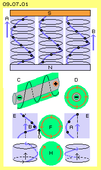 Left-Turning Current
At the second row of this picture at C is drawn a conductor-wire (grey). A current is running along from left to right side (so from minus to plus, see red arrow). Every current is embedded within a magnetic field (light-green), showing towards left (all times by view into direction of current). Thus also around a live conductor exists a spiral forward directed motion.
At third row at E now a situation is shown, where this current-carrying conductor reaches cross through the magnetic field, here from foreground to the background. This wire is a ´disturbing foreign body´ for the magnetic field. The aether-movements of blue magnetfieldlines collide with the movements of the light-green magnet-field F. Most important are the fieldlines which ´scratch´ against left and right edges of that foreign body.
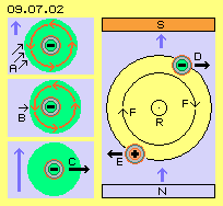 At picture 09.07.02 upside left at A once more is drawn the situation of current-carrying conductor within a magnetic field. Previous counter-pressure here is marked by three black arrows. As discussed upside, the magnetic fieldlines between the faces of north- and south-poles are ´stationary bound´ and thus relative ´rigid´. If this motion-pattern would swerve aside, the swelling would result wider surface towards the Free Aether. However the general aether-pressure pushes the magnetic fieldlines all times into that direction, where the way between poles is most short.
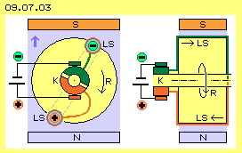 A steady turning of the rotor is achieved if the current-direction periodically is changing. The principle of that Direct-Current-Motor is shown at picture 09.07.03, left side by cross-sectional view and right side by longitudinal cross-sectional view through the rotor (R, yellow). Previous wires are connected at the rear side of the rotor and build a conductor-loop (LS). The upside section of the conductor is marked green. There the current flows from the foreground back, at longitudinal view from left to right. The below section is marked red and there the current is running from the background forward, at longitudinal view from right to left side (see arrows). Instead of that single circuit could be arranged many loops, building a coil.
At textbooks often is stated cross-the-board: "a generator is working by same principle like a motor, only by reverse affects". Here this would mean, previous device should produce electric current, if the rotor is driven mechanically. This is analysed by picture 09.07.04. Upside left at the picture once more exists a homogenous magnetic field (light-blue) between the north-pole (N, blue) and the south-pole (S, red). Within the magnetic field a rotor (R, yellow) is turning clockwise. At the rotor is drawn a conductor (grey) at four positions which it will take during the rotation of the rotor. Right upside at the picture are drawn three situations in details.
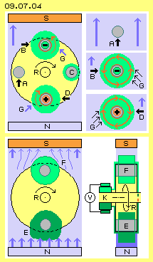 Quite different is the situation, when the conductor crosses the magnetic fieldlines, like marked by arrow at B. A counter-pressure (G, see arrows) comes up at the right side, which forces the aether into left-turn around the conductor. This would correspond to a flow from foreground backward. Unfortunately however the aetherpoints of the magnetic field come from the background forward. The spiral connecting-line respective previous ´thread-rod´ pushes the aether upward, however directed to the foreground. Thus no electric flow can come up.
Below at this picture 09.07.04 once more is drawn the construction of previous DC-motor, left side by cross-sectional view and right side by longitudinal view. The rotor (R, yellow) is right-turning by mechanical drive. Again a conductor-loop is installed at the rotor, where momentary a section E is positioned below and a section F is positioned upside. Again a fix connection exists between the wires of the conductor-loop (or a coil) and the two half-circles (light-green and dark-green) of a commutator K. Both halves of the commutator are connected with a voltmeter V via slide-contacts.
Previous DC-motor produces mechanical turning momentum, if current is fed. If however the same machine is driven by mechanical input, it does not produce current - but only some voltage is generated. Voltage is a ´potential´ which corresponds to the difference of charge-intensity. So strange enough this device produces charge of different strength in both sections of the conductor-loop. By view of the aether and based on previous considerations, this ´phenomenon´ might be based on two causes: the difference between magnetic north- and south-poles and the in-homogeneity of the magnetic field.
Common sciences can not explain wherefrom that voltage-difference should come. It must be charge-differences, however here is no source for charge-carrier. These whirls are not ordered so good, already a ´magnetic field´ could come up. It´s only just normal aether around the conductor. The appearance of ´charge´ only comes up because these whirls are impressed at layers near the surfaces. An electric flow finally comes up exclusively, when the Free Aether with its general aether-pressure flattens that accumulation of intensive aether-movements.
Picture 09.07.05 upside left at A shows the ´classic´ graph of induction-law concerning a conductor-loop within a magnetic field. Such loops respective coils are conventional elements for explaining electric ´phenomena´ and laws. Above this and as a rule, most electric devices function by closed circuits. So probably only an uneducated layman could produce the following considerations (and at the very moment I really do not know whether that idea is common practice or totally new).
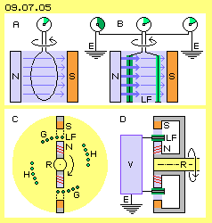 If loops or coils are used at rotating systems, the crossing of magnetic fieldlines occurs two times at each revolution, resulting alternating current. This ´one-arm´ charge-catchers are crossing the magnetic field likely, however the charge can flow off only into one direction, thus they deliver direct current all times. Below at picture 09.07.05 schematic is sketched a corresponding conception, left side by cross-sectional and right side by longitudinal view. It shows the generally preferred version of devices, where the current-carrying conductor is installed stationary within the stator and the magnets are arranged within the rotor.
Important now is the free space towards next group of charge-catchers. At the one hand, the magnetic field can calm down and restructure until the horseshoe-magnet next time is fed by previous DC-impulse. At the other hand this space- and time-section is necessary for useful work of the Free Aether.
The previous machine thus at first produces only charge, which by a second step is transferred into current. Naturally it would be preferable, if immediately the flow of electric current could be achieved. This question is analysed at picture 09.07.06.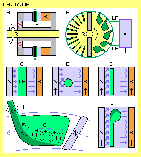 At C this arrangement is drawn by larger scale. Strong magnetic fieldlines exit from the face of north-pole (marked by thick blue arrows). The bolt (LF, green) should be near to the face of north-pole, however the distance to south-pole could be some longer. At D this situation is sketched by cross-sectional view at a round bolt. The vertical arrows show how the poles are moving relative to the stationary charge-catchers (here towards upside). There is also indicated a problem, as the magnetic fieldlines can ´slip-off´ at both sides of the round bolts (see split arrow). There comes up only such disordered whirls, like mentioned upside.
It might strike some readers as strange, the shape of constructional elements should be important for electric current. A comparison with fluid-technology might help. The particles of air are moving in chaotic manner, based on normal molecular movements. For example is demanded some power to push an air-plane forward. It demands only a certain shape of wings to organize an ordered flow, which finally produces a much stronger force for lifting upward the plane (for details see e.g. chapter ´05.04. Lift at Wings´).
09.08. Unipolar Machines
09. Aether-Elektro-Technics