Objectives
Physics-Graduate
The solution is presented most precisely: Capacitance C = e0*A/d, so the face A = d*C/e0, so A = 50*10^-6*1.0/8.8542*10^-12 mVmAs/AsV respective A = 5.65 km^2.
It´s noted: The result surely is unexpected concerning the size of the face. So no typing-error nor calculation-error, even the experimental verification e.g. would need all runways of Hamburg-Fuhlsbüttel Airport (marked yellow upside right at the picture.
Task 1.2: Calculate the volumina of mentioned Goldcap and the plate-capacitor of task 1.1, except the volume of the plate-material. A simple calulation offers the result: The volume of the plate-capacitor is 81 million times wider than the volume of the Goldcap. Unexpected here only is, why the task concerns the distance between the plates and excludes at least one mm of the plate-material (and thus would result many billions instead of only few millions).
For the Goldcap, the calculation is much simpler with its capacitance of 1 F and the voltage of 1.2 V. Charge = capacitance * voltage, so here Q=1F*1.2V=1.2 Coulomb. Energy stored is W=0.5*1.2F*1.2^2V = 0.72 Ws. So the Goldcap is clear winner with hundred-fold energy and million-fold higher charge and billion-fold higher capacitance.
What for such tasks are asked for graduation? To demonstrate the technical progress? Or to urge young people to learn by heart formula and data and to apply these most uncritical? I present these ´officially authorized correct calculations´, because I never would have dared to compare that Goldcap 1F 5.5V with a ´Fuhlsbüttel-capacitor´. That comparison can not be consistent: a copper surface of many square-kilometers can not be charged with some small batteries. That face would be a perfect grounding with practically unlimited capacitance. It would immediately ´suck-off´ all Hamburg power stations - by guaranty a super-GAU.
At modern electrolyt-capacitors also occur internal chemo-electric processes (and thus previous comparisons are questionable anyway). At the other hand, the laws of electricity where detected long times ago by using most simple equipment, just like that school-capacitor and even today can be replicated by such school experiments (however not quite harmless when using 5 kV). So the formula are suitable - and logically are matching, because all terms are defined by circle conclusions (as usual at physics). Also the measured results are fitting - because also the measurement equipment is standardized by mutual interdependence. So even this relative manageable subject of physics is investigated at its best, some appearances remain ´mysterious´. After that long time, could still remain some misunderstanding or misinterpretations?
Facts and Formula
Below left at the picture at D, the space between the plates is filled up by a non-conductive material (dielectricum, violette). Now one could assume, that ´massive´ restriction would hinder the electric field and indeed, again the voltage is measured essentially lower. So the conclusion was, using a dielectricum again will rise up the capacitance of capacitors. At the other hand results the statement, at given voltage the capacitor can take the more charge, the higher that capacitance. The ´relative permittivity´ is included into the capacitance formula C=er*A/d by a special factor. In comparison with vacuum respective air, diverse materials show different strength, e.g. Teflon with factor er of about 2, paper 3, ABS 4, Epoxy 5, porcelain 6, glass 8 and special materials many times more. The effect is explained by shifting of (positive/negative) charge at the surfaces of the plates and the dielectricum or within the gaps between (what´s most questionable, see below).
Contradictions
These are common known facts, followed by dubious statements: An electric current flows through the capacitor and charges one electrode positive and the other negative.. This can not be true, because an isolator just prevents the current. Within a capacitor, some charge may ´slop´ back and fro, at its best. The voltage is proportional to the charge stored. That´s wrong in principle: a voltage of 2 Volt can result of 5002-5000 or 12-10 or 2-0, however never by the difference between +1 and -1. No matter how often it´s repeated at textbooks: no positive charge can exist, no ´positrons´ are existing, even at semiconductors exist only ´gaps resp. ´vacance-electrons´ (even school-graduates are told). That thinking by plus/minus is categorically wrong and results totally false ideas.
If one puts the plates of a charged capacitor nearer to each other (e.g. below at the picture the plates F and G), a certain force is demanded. This contradicts the rule, that plus and minus are attracting mutually. Opposite, that counter-pressure is an indisputable approve for the fact, the charges at both plates must be negative (because likely charges indeed are mutually rejecting).
So at both plates can exist only negative charges. Normally both charges are different strong, i.e. each plate shows an other voltage versus the earth. The voltmeter between the plates shows the relative voltage between. It marks the power by which the general Aether-pressure would balance both charges, if both areas would be connected with a conductive wire (see chapter 09.04. Charge). So here only the statement is correct, that voltage is proportional to the difference of negative charges at both electrodes (no matter at which level). The smallest voltage versus the earth is null. However even that plate still is charged - just like the charge of every materia at this place near the earth ground at this moment.
At the middle of that picture 09.13.03 schematic is drawn the real situation after charging a capacitor. Each charge generates an electric field within its environment. These ´charge-clouds´ here are marked by light-green areas. The plate D is surrounded by a thick layer of charge, the plate E shows a smaller ´aura´. The difference is marked by the voltmeter. The noticed ´phenomenon´ now is, the voltage becomes lower if the plates are moved nearer to each other (see arrows at F and G). As mentioned upside, this would mean same time an increased capacitance. A simple and logic explanation is only possible when understanding the aether as a real substance and charge as a certain motion-pattern of aether within the aether.
Real Aether-Movements
Charge is not only a ´fictive field around a solid electron-particle´. The charge by itself is an area of ordered aether-swinging (and electrons are only a ´round trop´ of corresponding motion-pattern). Opposite, the ´Free Aether´ of the environment has no certain structure, but its movements occur at short sections of varying tracks (e.g. resulting from the multiple overlays of all radiations running through the aether). That chaotic whirr rattles from outside towards the areas of ordered aether movements. Therefore the flat motion-pattern of charge is pressed onto the surface of the electrodes. The stronger the charge, the wider its motion-structure reaches outside into the aether-space. The general aether-pressure also affects a most even layer of charge at a material surface. That´s why e.g. voltage-differences become balanced in shape of current along conductors (as described in details at earlier chapters).
Charge is a synchronous swinging of aether above a conductor face. The intensity of movements becomes weaker from the face outward. Finally exists a smooth transition to the Free Aether. At previous picture these areas are marked light-green around the electrodes. There are marked dark-green borderlines, representing that smooth transition to the Free Aether. So between the capacitor-plates does not exist one electric field (between plus and minus) but there meet two (negative) charge-areas.
Charge is an aether-swinging with a left-turning stroke-component (details see earlier chapters). At the inner, opposite positioned faces both swinging motions are running by contrary directions. At the border between both areas comes up ´stress´ (because no contrary movements are possible nearby each other within the gapless aether). Both motion-pattern reject mutually (like known e.g. by two neighbouring negative ´spot-charges´ of common understanding).
Mis-Interpretation
A quite fitting example can help to understand that reaction: if two air-balloons are blown up by different strength and now are pressed towards each other, the internal pressures of both balloons become balanced. The volume of the previous smaller balloon becomes enlarged and thus the difference between both balloon-surfaces becomes smaller.
If - at unchanged charges - the voltage between both plates decreases, the capacitance of that arrangement must increase, corresponding to capacitor-formula Q=C*U. With that formula-bound thinking, that symptom of weaker voltage is interpreted totally false. The volume between the plates becomes smaller, so also the ability for taking charges at that area. The charge is unchanged, it´s only displaced within space, towards the ´bulge´ at the edges and towards the backward face of the plates and along the wires towards the voltmeter. That suggested ´capacitance-factor´ even is a yardstick for the limitation of charge-storage. If a capacitor cushions the voltage-variations, its ´electric capacitance´ even marks the ´degree of hardness of the spring respective shock-absorber´.
If that capacitor is installed within an AC-circuit, subsequently will come up stronger voltage at right plate (see below right side at C) and both charges now are shifted towards left. So it looks like the current would run through that capacitor, alternating from left to right (at B) and back again (at C).
At this picture below left at D is sketched, why both negative fields reject each other. All charges swing synchronous left-turning all times, by view from the surface outward (like here marked by the circle-arrows). Between the plates (at E) both movements meet contrary. This results ´stress´ within the gapless aether, which is only to avoid, if both charge-areas move to a sufficient distance.
At the upside bulges, both charges swing likely left-turning. Finally some below at the ´bay´ between both charges, the movements become contrary turning. If however a current-peak comes up too strong (or if too much charge is pressed into the capacitor), a short-circuit will result. The extensions of the volumina aside build a common round face (marked yellow below at F). All charges now are left-turning aside each other and are swinging synchronous (see neighbouring circle-arrows there). Both charges suddenly become balanced respective a short occurs, where current immediately can flow from source to sink without resistance (see arrow at F).
Dielectricum
At this picture, the red plates are charged only ´by half´, so there is still some space (white) towards the dielectricum (violet). The green plates are charge ´full´, so the charge-layer reaches up to the dielectricum. The suggested higher capacitance thus realiter is a strong limitation for the ability to take charge. Such capacitors of extreme high capacitance can work only within a narrow size of voltage, e.g. from 2.5 to 2.7 V. If more charge is pressed into such capacitors, the necessary charge-layers become inflated - until the capacitor ´explodes´. ´The ´voltage-resistance´ thus is an essential criteria. Naturally one can shift charge into the narrow gaps between the plates respective dielectricum. The ´elasticity´ concerning the balancing of voltage-peaks however is very small. If the capacitor is charged ´full´, the Free Aether has no ´point-for-attack´ to push-off the charge again. So a buffer for charge practically exists only at the outside faces and the wires towards the electrodes.
Right side at the picture at C, the space between the plates is filled up with a dielectricum nearby completely, so the swinging motion of the charge is most restricted. The charges are pressed off towards the outside faces of the plates. If now from left comes higher voltage (see arrows at C), the ´bulge´ can not arch towards right over the dielectricum. The ´elasticity´ for buffering voltage-variations thus is strong limited.
At this picture at D is sketchen an isolator (DI, violet) for high-voltage conductors. If the isolator would be build simply as a cylinder, charge could run towards right side at voltage-peaks. At that typical shape of ´pyramid-cake´, charge occasionally can swop over the first hurdle (see arrow). That part of charge is pressed into the ring-shaped depression by the general aether-pressure (see thick arrows). Occasionally parts of charge can also climb over the next ´hill´, where again they get trapped by the Free Aether. Finally these parts of charge will ´evaporate´, because their motion-structures at the isolator-surfaces are not homogeneous and not stable longterm. The Free Aether will it ´wear-away´, i.e. these areas will become unstructured motions like the aether of the environment.
Coulomb-Forces
The real cause of that ´Coulomb-force´ is as follows: at E both charge fields are positioned upside of the dielectricum. Further upside exists the smooth transition to the Free Aehter. The Free Aether thus can affect pressure only indirect onto the upside face of the dielectricum (see thin downward-arrow). Direct however the pressure of the Free Aether can affect onto the below face of the dielectricum at E. Within theses ´rugged faces and disorderly charges´ exist many spots of contrary movements with corresponding ´stress´ at the gapless aether. Corresponding strong affects the aether-pressure onto the below face of the dielectricum (see thick upward-arrow).
Below right side at F, the reverse situation is sketched: the dielectricum must be drawn off the plates against the strong pressure of the aether (which here is directed top down). So the dielectricum is not drawn into the gap between the plates by a suggested attracting force (by assumed positive / negative charge carriers), nor it is kept within the plates by a suggested attracting force. In reality, based on the real substance of the aether, only pressure forces are working all times. Here they shift the dielectricum into the gaps between the plates (at E) and hinder the taking-off (at F). Both forces neutralize each other. So as a whole, no input of power is necessary for moving a dielectricum through a capacitor.
This is a rather critical situation for commonly valid theories of physics: in total no power-input is demanded for shifting a dielectricum through a plate-capacitor. However this process changes the charge and/or the voltage, thus changes the energy stored, where the factor voltage acts by square, thus it comes up the ´danger´ situation, one could build a perpetuum mobile. Naturally that possibility is explained away, occasionally with the remark, the scale of forces anyway is negligible small (what theoretical still would be a clear violation of the law of energy-constant).
Sphere-shaped and round Capacitors
At picture 09.13.06 is drawn a sphere (A, grey) with conductive surface. When this sphere is charged, an area (B, light green) of synchronous swinging comes up all around. At the conductive face the swinging movements are intensive and they are weaker towards outside until the smooth transition to the Free Aether of the environment. Simplistic one can imaging a border respective a membrane (dark green): outside of exists chaotic motion, inside of exists ordered swinging. The aether is everywhere the same, only the characteristic of its internal movements are locally differing.
If however a conductor (D, grey, with less charge) come near to the ´charge-membrane´, the ordered motion-structure becomes disturbed. Charge (here marked red) flows off along the conductor and implosion-like the aether-pressure concentrates (see blue arrows). Extreme high voltage discharges via sparks. Short time later, that ´chaotic´ flow is cut off by the aether-pressure aside and the remaining charge again is pressed concentric at the sphere-surface (E). That spark-gap is wanted at some applications. If however a sphere should work ´soft´ as a capacitor, suitable ways for charging and discharging are demanded. An alternative e.g. could be a copper-pipe (F, with closed ends or at least round edges) or a coil (G, which anyway has a certain ´capacitance´).
At H is shown a cross-sectional view through a sphere respective a pipe. A first volume of charge (green) encloses the surface. If an additional ´charge-portion´ (red) is put at the surface, only a relative small extension of the ´border-face´ is necessary. Each further charge (blue) can be loaded at the face with less resistance against the ambient Free Aether. Opposite, the Free Aether can affect concentric pressure for discharging and the charge will flow off by high voltage most fast. So these round constructional shapes are most suitable for temporary storage of charge.
Double-Pack
Below right sided at this picture at D, previous school-capacitor is drawn once more. The left plate was charged by 5 kV (green), while the right plate shows only minimum charge (red). The strong charge reaches far out and is sticked also at other near surfaces by the aether-pressure. The whole arrangement becomes embedded within a ´charge-cloud´. Even no conductive connection exists, the area between the plates actually builds a Faraday-cage (yellow). The voltmeter between both plates will show only few voltage - might be by size according to the (general wrong) formula. Few voltage means high capacitance (according to formula) - however the real capacitance between the plates is virtually null.
Misunderstanding
If a conductive face becomes charged, no electrons are shifted onto the surface. However the aether around the conductor and at its environment is put into ordered swinging. The energy of that motion is identical to the electric field. The amount of 1.6 * 10^19 electrons is only the arithmetical pendant to the charge of one Coulomb.
My grave misunderstanding probably was taking the term ´capacitance´ literally as ´ability for taking charge´. The terms ´charge/capacitance/voltage´ of capacitors however concern only the processes between the plates. They describe only the volume of ´sloshing-to-and-fro´ of charge respective are only index-numbers for the ´hardness´ for the cushion of voltage-peaks. Probably some of previous arguments will be useful for better understanding of real processes. Simply the vision of these two air-balloons might help also the experts to get reality-conform ideas.
For me, previous analyses resulted the insight, conventional plate-capacitors are not suitable for generating current. There are demanded charges as much as possible, which are stored at free standing and round faces at its best. At the other hand these considerations achieved the clear understanding, that and why and how one can manipulate these ´charge-clouds´ reaching out into the aether-space. For example, the ´space-for-motions´ can be diminished essentially be using a dielectricum (by minimum input of power). A strong interaction also comes up by using a second charged surface - until the total displacement of charge at a Faraday-cup.
Calculation Example
The second row shows the second phase: one half of the charge of storage C2 is shifted onto the charge-storage C1 (marked yellow). By using a dielectricum and/or an other charged face, thus charge must be pushed off C2 and loaded onto C1. As discussed upside at picture 09.13.06, round storage faces are most suitable (and possible technical constructions are discussed at next chapter). After that charge-shift exists increased charge of 0.09 C at storage C1 and this corresponds to a voltage of 1050 V against the earth. Storage C2 now shows a decreased charge of about 0.03 C, corresponding to a voltage of only 350 V against earth. Between both charge storages thus momentary exists a relative voltage of 700 V and a charge-difference of 0.06 C.
Based on the resistance (in Ohm) and the capacitance (in Farad) results the discharge-time (in seconds) by formula tau=R*C. After 5 time-units tau the balance is completely achieved. That time here should be limited at maximum 0.02 seconds. After the first time-unit tau already 63 % of the charge are flown off. That first part of time is valuable, because the main part of charge flows by high voltage. Thus one time-unit tau here should be previous 0.02/5 = 0.004 s long. By reorganisation of previous formula now the capacitance can be calculated: C=tau/R, so here C=0.004/50 = 0.00008 Farad. 1F=1As/1V, so 1As=1F*1V. For the wanted voltage of 220 V results a current-power I=0.00008*220 = 0.017 As. So about 0.02 Coulomb must flow within the first tau-time-unit.
At the beginning of the discharge-phase, the difference of voltage is 1050-350=700 V. At the end of discharge, both storages again show each 700 V (against earth), so no voltage between the storages. The simple average value is (700+0)/2=350 V. That decrease of voltage from 1050 V by 350 V to 700 V is marked below left at this picture. Within the first time-unit the decrease is 63 %, so about 220 V. Same time the difference of charges (0.09 C versus 0.03 C) becomes balanced (to 0.06 C at both storages). So flowing are 0.03 Coulomb, of them at first tau-time-unit about 0.02 Coulomb. Based on these figures result the wanted 700 V and 0.06 Coulomb as necessary first charge.
Naturally the check-calculations are matching with the initially demanded data. The power of current is I=Q/t, so here I=0.02/0.004 = 5 A (rounded, corresponding to previous 4.5 A). Also the performance P=U*I, so here P=220*5 = 1100 W corresponds to previous guideline (some rounded). Based on formula for energy W=0.5*C*U^2 for this potential are resulting W=05*0.02*220^2 = 480 Ws.
The first time-unit of discharge takes only few milli-seconds, the complete balance of charges however takes about two hundredth seconds. If one could achieve hundred of such current-impulses each second, four of these arrangements must work (each time-shifted). This would result 480*100 Ws or about 13 kWh, as an estimated cross amount for this example. That figure must be reduced by the demanded energy for drive, for losses by friction, at the conductors and for additional demanded constructional elements. So about 6 kWh could be achieved at its best. If these considerations are not totally wrong, usable performance could be achieved.
Charge and Voltage
Starting point is a conductor-face (dark green) of 1 m^2 and above a space of 1 m height. Within that volume of 1 m^3 a charge of 1 Coulomb shall exist in shape of synchronous swinging aether. At the upper face of that volume ´lasts´ the general aether-pressure of 1 V (upside yellow face). So opposite is valid: if that conductive face is charged by 1 V, the charge of 1 C is put onto that face and the field aboce is still measurable at the height of 1 m.
As an equivalent for 1 C is defined the amount of 1.6*10^19 free electrons. An idea of these ´astronomic´ numbers might show following comparison: the radius of an electron is assumed by about 10^-15 m, i.e. at the length of 1 m could take place 10^15 electrons (theoretical, one beside the other). If that cubic meter would be a huge store, 10^45 places for electrons would be available. However only 10^19 places would be occupied (for this one coulomb) and thus besides each electron would exist 10^26 free places. In reality, the field exists not by separated electrons but is a swinging pattern of all aether within that cubic meter. These ordered movements of charge thus are an extreme ´soft´ swinging within that gapless substance.
A further compression into vertical direction is not suitable because the voltage increases exponentially (and the charge is pressed off aside, up to the effect of a Faraday-cage). Or at the other hand, much less charge could be stored by likely voltage within that narrow space. If one wants to manipulate the charge, the major part of charge-swinging exists anyway up to 5 cm above the conductive face (and even more when using an isolating lid).
By lowering that cover, the sum of all energy of the aether-swinging keeps constant. The previous sketched spiral lines (picture 09.13.07 right side) become shorter and corresponding wider become the amplitudes (actually like a spring would be compressed like a screw). The swinging however still is rather soft and allows further (linear) compression, e.g. by reduction of that face of 1 m^2 to these 314 cm^2 of previous school-capacitor. That face is about 32 times smaller and correspondingly denser is the swinging motion (visually spoken: more ´spiral-springs´ fit into the volume, when they are arranged some shifted in vertical direction). The voltage-pressure rises to 31*32, so up to about 1000 V (see picture below right side). So within that volume of about 1500 cm^3 respective 1.5 liter, the charge-amount of 1 Coulomb can be stored by charging with 1000 V.
This is much more than the two, three or nine hundredth Coulomb by voltage of 220 up to 1050 V of previous example calculation. So one does not need 565 km^2 for one Farad or 5kV for tiny small charge amount at the school-capacitor. Already with 1000 V one can store 1 C at a small conductive face (with few centimetre room-to-move for the swinging motions of the aether). Afterward one can shift the charge to-and-fro with few input of power (as approved by previous discussed shifting of a dialectricum between the capacitor-plates). That´s no ´unexpected´ result, because e.g. 1 Ampere by 220 V is running along each normal conductive wire without problem, respective the corresponding charge is shaked to-and-fro by 50 Hz at common power supply. Based on these considerations, new points of view and described facts, the technical realisation can be discussed at the following chapter.
In 2003 I made up a conception for an ´Electrostatic-Currentgenerator´ (see animation), where current should be produced by shifting charges. The capacitance and voltage of capacitors are changing, when a dielectric material is put between the plates. Thus within a rotating system, current should flow from the plate with momentary few capacitance to the plate of momentary wider ability for taking charge. Experts confirmed the correct application of valid laws, nevertheless that conception was a real flop. Since last year, I consider consequently the electric appearances as motion pattern of the aether, so now that capacitor problem must be analysed once more.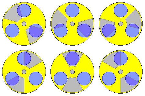 Today, capacitors are used in nearby every electric / electronic unit by diverse shapes and for most different functions. Obviously these constructional elements are working without problems, so the basic electric laws must not be questioned any longer. Nevertheless some properties and reactions of capacitors seem somehow ´mysterious´. Probably many readers will find their own questions of (non-) understanding at the following considerations. Starting base will be a ´handout for high-school diploma in physics 2011´, which was published by the authorities for Hamburg´s schools, with exact examples of tasks and precise solutions (here qouted in italics). Afterward supposed contradictions at common doctrines of textbooks (or lots of at the web) are examined. Clear causality finally results by the view of aether and its motions. The final conclusions will allow the conception of real working current-generators, like discussed at the following chapter.
The mentioned ´handout´ concerns the comparison of a modern capacitor (see picture 09.13.01 upside left) with a conventional plate-capacitor. General part: a ´Goldcap´ is a capacitor with high capacitance, which shows rather small dimensions in comparison with a foil-capacitor. A certain type shows following data: capacitance 1.0 F, size of cylindrical housing: diameter 21 mm, height 10 mm. Task 1.1: Calculate the size of a plate-capacitor, which has a capacitance of 1.0 F, where the distance between the plates is 50 micrometer. Calculate with the dielectric-constant of vacuum.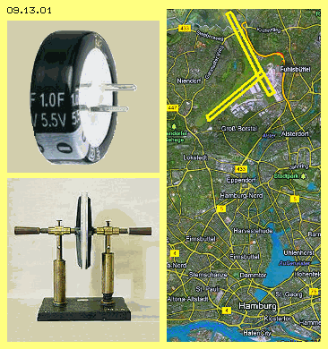 The third task is a clear comparison with known plate-capacitor (see photo of school-museum at picture 09.13.01 below left). Task 1.3: At a school-experiment with a plate-capacitor the face of plates is 314 cm^2, the distance between is 2 mm and the voltage for charging is 5 kV. Compare the capacitance of that plate-capacitor, the charge at the plates and the energy stored with the Goldcap 1 F charged by 1.2 V. Here again is asked the known capacitor-formula C=e0*A/d, calculating with the data 8.854*10^-12 and 314 cm^2 and 2 mm, resulting C=1.39*10^-10 F. The charge Q (in Coulomb respective Amperesecond) is capacitance C (in Farad) multiplied by Voltage (in Volt), so here Q=1.39*10^-10*5000 = 0.000000695 Coulomb respective 695 nC. For the energy stored is valid the formula W (in Joule resp. Ws) = 0.5 multiplied by capacitance (in Farad) multiplied by voltage by square, so here W=0.5*1.39*10^-10*5000^2 = 0.00174 Ws resp. 1.74 mWs. In spite of applied high voltage that old plate-capacitor obviously takes charge only in the size of micro-Coulomb and energy respective work only at the size of milli-watt.
At the following, only these simple plate-capacitors are discussed by investigating common doctrines of textbooks (again quoted in italics) in order to detect hidden contradictions. At picture 09.13.02 four capacitors are shown schematic. Upside left at A one plate is charged negative (green) and the other positive (red). A voltmeter (VM, blue) shows the voltage between both plates. The charge Q can rise up, the more capacitance C is available and the higher voltage U is applied (corresponding to formula Q=C*U). It´s obvious, a face twice as wide (upside right at B) will show double ability for taking charge. With likely voltage, thus the capacitor can take corresponding more charge.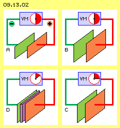 Below right at this picture at C, both plates are moved together to half distance (everything else is unchanged). As a result, the measured voltage is also lowered to half. As the charge within that system is unchanged, the capacitance now must be double, according to Q=C*U. So it was concluded and defined, the capacitance is proportional to the face and inverse proportional to the distance between the plates (thus C=A/d is valid). That´s rather astonishing respective merely to understand: as the space becomes more narrow, yet the ability for taking charge increases.
Once more from the beginning: Capacitors are used in diverse shape for different purposes. Generally however a capacitor balances changes of voltage. Capacitors have the ability to store charge. That´s called ´electric capacitance´. Generally a capacitor is build by two electrodes, in simplest case by two copper-plates. As a rule, between the plates exists a layer of non-conductive material, called ´dielectricum´.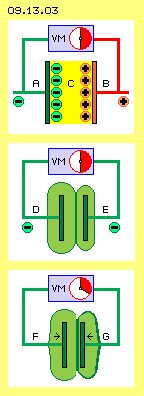 At picture 09.13.03 once more are sketched some capacitors, each with two plates and a voltmeter (VM, blue). Upside is drawn the conventional idea: one plate (A, green) is charged negative and other plate (B, red) is charged positive, as ´charge-carriers´ are sticking at the surfaces. Between exists the electric field (C, yellow), which has an attracting force into direction of the plus-electrode. If however no positive charge exists and no positive charge-carriers can exist at all, and one can not really imagine any attraction through the ´nothing of space´ - these ideas can not match the reality.
Already the statement, an electric charge is generating an electric field all around, is questionable: the charge at the surface is not bound to the existence of free electrons, but the charge is identical with the electric field. The statement, the field is a property of the space and does not nead a carrier for the effecting forces, thus can also exist within the ´empty space´, is not tenable: materially affecting forces can not be transmitted through ´nothing´ (and by sure not the imaginary attraction-forces). Fields can only work through the real substance of aether (which indeed is the unique existing material stuff) and forces can only affect as internal movements within the aether.
If the distance between capacitor-plates decreases, also the voltage decreases. That effect schematic is drawn at picture 09.13.03 (see arrows F and G). That ´phenomenon´ is easy to explain: the stronger charge-volume of the left plate presses the weaker charge volume of the right plate to the backward face of the right plate. Its original relative small volume becomes wider and now it shows a wider surface. The Free Aether presses charge via conductive wire to the voltmeter in relation of both charge-surfaces. Their difference now is smaller and thus the voltmeter registers a smaller voltage.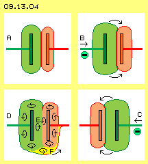 At picture 09.13.04 upside left at A, the initial situation is drawn. The left plate is stronger charged than the right one (here each weaker charge-aura is marked red). At B (upside right at the picture) the voltage from left side increased, so both charges were shifted some towards right. If afterward the voltage at left side decreases, both charges will spill back. That´s the procedure how voltage-peaks are cushioned within electric circuits.
In order to achieve even higher ´capacitance´, multilayer-capacitors were build, like schematic shown at picture 09.13.05 upside at A. Several plates are installed at the electrodes, comb-like arranged and each separated by a dielectrical layer. Both sides of each plate can take charge, so rather wide conductive surfaces can be build within small constructional volume. As the distance between the plates is rather narrow, such capacitors show high capacitance according to the valid formula.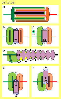 Left at this picture at B, a simple plate-capacitor is sketched, where a dielectricum (DI, violet) is included. By common understanding, its permittivity increases the electric capacitance and lowers the voltage between the electrodes. There are different attempts for suggested explanations. Logic and real is only that fact: also at the surface of an isolator exists charge. However at the amorphous surface can not come up homogeneous layers of swinging movements. Within the ´rugged valleys and hills´ exist spots of charge of different strength and direction. From these multiple small faces outward exists an jumble of aether-movements (here represented by the blue jagged peaks).
´Universal Aether-Pressure´ is called that power, by which the Free Aether affects onto ordered motion-structures. The enormous power one can feel directly, if one holds north- and south-poles of two bar-magnets in short distance (see chapter 09.06. Magnets). If one feeds a dielectricum between both plates of a capacitor, a corresponding effect comes up. At picture 09.13.04 below at E a dielectricum (DI) is put between capacitor-plates from bottom up. Strange enough, the dielectricum is ´pulled´ into that gap (see thin upward-arrow). Opposite, some force is demanded for taking off again the dielectricum, e.g. at F towards upside (see thin upward-arrow).
The theorists are also bothered with sphere-shaped charge-storages:
a free standing sphere is a special case as the counter-electrode is far off, e.g. build by the earth-potential. The capacitance of these constructional storages is very small - if the general formula Q=A/d*U is applied. In practice however the capacitance is higher, a sphere can be charged up to millions of volts, before a spark-discharge occurs. The sphere is no ´special case´ but its properties document most clear, the common formula does not match with the real processes.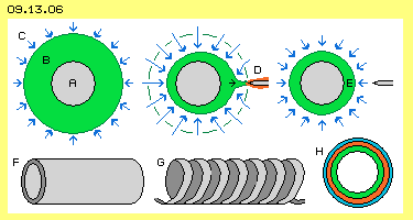 The sphere-shape is ideal for storage of charge, because the volume of ordered swinging is enclosed by a most small surface. The general aether-pressure (C, represented by the blue arrows all around) presses that motion-structure concentric at the sphere. As long as the enclosed motion shows a stabile structure, the outside pressure can not compress that volume further inward (or can not disperse it).
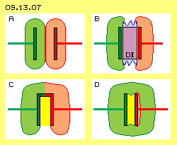 Picture 09.13.07 shows an other extreme case: both plates are charged likely strong (at A, green and red marked only for differing the fields). So no (or only minimum) difference of voltage exists between both plates. Based on common formula, the capacitance should be nearby infinite. If in addition a dielectricum (DI, violet) would be included (at B), the capacitance theoretical should be once more increased. If no voltage between plates exists, they could also be connected by a conductor (like shown at C). A ´Faraday-cup´ would result - with null capacitance for charge between the plates (marked yellow). Thus also this case clearly shows, the common capacitor-formula is not valid at all.
The capacitor-formula does not portray the real facts correctly. Quite clear is measured the decrease of voltage when the plates are narrowed, however the false conclusions were drawn from that symptom. Totally false ideas are resulting from the (on and on repeated) idea, any positive charge would really exist. Also one still believes, current would be based on the movement of electrons along the surface of conductors. The basic problem at capacitors is the conviction, the plate becomes charged by putting electrons at the conductive surface and afterward the electric field would be build. That duality does not exist. Well, there are free electrons and their motion-pattern is sketched at picture 09.13.08 at the left column. The S-shaped connecting lines represent neighbouring aether-points, which are synchronous swinging all around (see arrow). Only by that motion structure, all movements within that volume are totally balanced. At the border of that symmetrical motion-sphere, the aether is ´resting´ respective there exists the smooth transition to the Free Aether. All cross-sectional views through that volume show identical characteristic. At this picture are drawn three phases of the movements (see red marked curves) and previous animation shows that process.
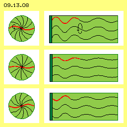 The motion-pattern of charge is sketched at the right column. There are likely S-shaped windings, which however show outward from the conductive surface (dark green) into the aether-space. All aether is swinging parallel to each other, where the amplitude of motions becomes smaller towards outside, until the smooth transition to the Free Aether.
Upside school exam brought correct however most questionable calculations. Hopefully the following calculations will result a realistic scale of data. Based on expected figures of a discharge process, the necessary values for the charged status are estimated. Picture 09.13.10 shows facts and data, at the upper row at first the starting situation: two free standing (copper-) spheres (C1 and C2, grey) are used for storage of charge. Both are charged by 700 V (against the ground). So between the spheres momentary exists no voltage-difference. Each amount of charge is about 0.06 Coulomb (green and red area). So that first charging demands a current of two times 0.06 Ampereseconds.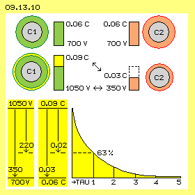 At a third phase occurs the balancing of charges between C1 and C2, so afterward both charge storages again will show the starting status. The data and the discharge-curve are sketched below at this picture. By the act of discharging, a usable current should be achieved, for example a performance of 1000 W by commonly given 220 V. The wanted power of current is I=P/U, so here an amperage I=1000/220 = 4.5 A. The consumer could represent a resistance R=U/I, so here R=220/4.5 = 50 Ohm.
At common capacitors mostly exist extreme small values of charge, capacitance or voltage. So it´s the question, whether these free standing charge faces can provide the necessary high capacitance and voltage. Picture 09.13.11 shows some figures by graphs.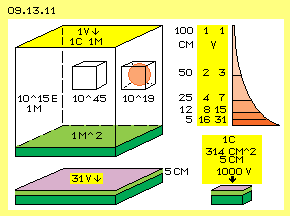 The charge is not spread equal within the volume. Near to the conductive surface, the intensity of swinging is most strong and decreases (probably) with the square of the distance (see red faces upside right at this picture). If one lowers down the ´lid´ of that space to 50 cm (e.g. by a dielectricum, yellow), the voltage is doubled. Based on common formula e.g. at 5 cm distance already would exist 20 V. I suggest one should accumulate the increasing voltages of that compression (at each half of the distance e.g. 1+2+4+8+16), so at 5 cm about 31 V would result. So one needs about 31 V to put a charge of 1 Coulomb into that space of 100*100*5 cm = 50 liter (below left at this picture, dielectricum ´lid´ violet).
09.14. Electrostatic-Ring-Generator
09. Aether-Electro-Technics