Ultrasound-Missile
One well knows, this explanation is not really sufficient. For example, also around the projectile comes up a magnetic field, again left-turning, thus showing downward at its backside (left). Within a fluid, three parallel flows would produce ´suction´ - and analogue one can imaging the ´flowing´ of magnetic fieldlines. Thus the projectile would be pulled towards the source of the current and would not be pushed off. However these guns practically function - even no clear knowledge about the theoretic functions exists.
Ball-Bearing Motor
Walter Thurner e.g. build an unipolar-machine, where the electric contact between stator and rotor was realized by balls running around. In general, this corresponds to previous conception, however added by the magnets of an unipolar-machine at the central area. The machine did work as a generator with good efficiency. However the drawing-off the current via rolling balls made some problems, e.g. as heat comes up. Opposite, if current is fed into the system, the machine did work as a motor, accelerating up to 10000 rpm - until self-destruction. Obviously come up great vortices within surrounding aether, resulting that self-acceleration and merely to control.
The reports about appearing effects are contradictory. However it might be true, ´levitation´ was coming up and some of Searl´s discs did fly off. Probably some later, Searl was able to control the acceleration. At any case came up electric voltages and flows. Many speculations exist about analogue appearances at UFOs. Probably Searl was able to build reliable working current-generators. As a whole however, the stories about John Searl are so confusing, they can not be used as a basis for analysing the decisive effects.
Better documented are the experiments of Wladimir Roschtschin and Sergej Godin. They build stationary rotor-systems, somehow analogue to Searl respective corresponding to these sketches in general. They measured weight-losses up to 35 percent. At the bottom, the generated aether-vortices are affected by stronger resistance than at the top. The ´stress´ at the bottom lifts the whole system upward. The aether-vortices showed effects also within neighboured rooms and upside floors. Without any doubts, self-acceleration did come up, so Roschtschin/Godin did take care to limit the revolutions of the system to only 600 rpm.
That ´magnetic energy converter´ (MEG) had a diameter of about 1 m and achieved a performance of 7 kW. Unfortunately that unit for usage of ´free energy´ still is not available. Probably also here the magnets are build too complex. In general, long term rotating permanent magnets become fragile. Based on these problems, also these well documented experiments can not show the true cause of generated effects.
Simple Runway
Especially by the cross-sectional view at B it´s apparent, there is no clear way for the back-flow from north- to south-pole. The magnetic fieldlines e.g. leave the left north-pole and can take the upside way to the left south-pole, however can enter only from aside. Symmetric can run the back-flow of the magnet right side. Both magnetic fieldlines however meet contrary turning at their south-poles. Above this, the magnetic back-flow is hindered aside and below by the rails and their magnetic fields. When that cylinder is rolling along the rails (and it does indeed), even more complicated aether-vortices come up. So also this arrangement gives no clear picture for the decisive aether-movements.
Rolling both Directions
This experiment is most simple and the result is just ´incredible´. At a congress or workshop I witnessed that experiment and tested it by myself. I clearly remember the astonishing result, even I was not involved in electromagnetic appearances of the aether at that time. So unfortunately I do not know, where and when and who demonstrated the experiment. At the other hand, everybody can repeat it respective it should be basic-equipment at every school. All students must learn the rules and laws of electromagnetism, which are proven by experiments and the effects are explained at its best. It´s also pointed out, these explanations are only ´mental models for easier understanding´. And just here this experiment would fit - because obviously showing, the ideas of common physical understanding are totally over-strained respective are excluding the most decisive aspects.
Charge-Shell all-around
Previous chapters already did show how far the static charge can reach into the space, e.g. when rubbing a PVC-ruler with a wool-sheet. So relative small voltage will be sufficient to cover the device completely with a ´charge-shell´. The aura of static charge here is marked light-green. The swinging-pattern of static charge was described at previous chapters e.g. at picture 09.05.02. Generally, starting from the surface, manifold wounded connecting-lines are directed into the neighbouring space, swinging synchronously, the further outward by each smaller size. The Free Aether presses that motion-pattern towards the surfaces, so that motion-layer shows likely height all around. Upside of the cylinder thus a ´charge-hill´ comes up and also aside of the cylinder these aether-movements reach some further out into the space.
Aether is shifting Mountains
The ordered and wide-swinging motion-patter of the charge becomes wider by the rolling cylinder and the border-surface of that aura also becomes larger against the Free Aether. Some time later thus increases also the effective face for the general aether-pressure. As soon as a ´weak-spot´ comes up, the charge-layer will be pressed nearer to the surface again. At the rear side of the rolling cylinder, its charge is drawn off the (here rather flat) charge-layer upside of the rail. Into that area of relative weak aether-movements, now the Free Aether can affect pressure, like marked by the blue arrows. So in front of the cylinder occurs an expansion of the motion-aura (see red arrows at F). At the back end, the cylinder is rolling off and the volume of involved aether is reduced (see blue arrows at G). At the front, the spiral swinging of the cylinder-charge and the rail-charge are crossing, i.e. both as a whole will reach out rather far. At the rear end, both motions become separated, so there the swinging layer becomes weaker.
Current follows Voltage
At chapter ´09.05. Current´ e.g. at picture 09.05.04 was shown, how the general aether-pressure pushes the charge-hill of DC along a conductor - nearby with speed of light and minimum loss. Here at this experiment, the electric source installs a uniform charge-layer at the surfaces. However above and aside of the cylinder the layer is enlarged, thus building an ´artificial´ charge-hill. When the cylinder is resting, that layer hangs symmetric around that hill. If the cylinder gets rolling, an asymmetry comes up and the Free Aether pushes that charge-hill forward, inclusive the embedded material cylinder - just like the charge-hill from the DC-generator. When current is moving along a round conductor, the enlarged charge builds a ring-shaped expansion. Here the cylinder can build a hill only at one side above the rail. Here the cylinder is drawn with an oval cross-section which might show best effects, as the charge at the front side is ´sqeezed´ upside-out and at the rear end the aether-pressure can affect concentrated into that deepening.
With concern to the speeds, however grave differences exist. At AC at first occurs the extension of the charge (producing the voltage) and already 0.005 s later starts the compression of that hill. Here the cylinder must roll forward one diameter until the outward pressed motion of the front side can be compressed again behind the cylinder. If the cylinders has a diameter e.g. of 5 cm, it must move forward e.g. by 10 m/s to achieve previous frequency of AC. As long as the cylinder is rolling slow, the potential of the aether can affect only by parts. Nevertheless the cylinder becomes accelerated, however the aether can drive much higher frequencies. The faster the cylinder rolls, the higher the hill at the front-side is piled-up and thus the stronger works the following aether-pressure, pushing the cylinder forward. At optimum conditions thus the cylinder will not accelerate linear but progressive. This is told how railguns do and thus should be possible also at rotating systems.
Excursus: Relation of Speeds
The sound-barrier often is the limit for our technical applications, e.g. as airplanes travel little bit slower than 300 m/s. If a rotor has a diameter of 1 m, that speed at the rim is achieved by 18000 rpm. So ´technical usable´ are only speeds, which are 1000 times slower than the cruising speed of the earth. So if a mechanic constructional element is moving thus fast, its atoms wander through the aether 1000000 times slower than the aether internal is moving anyhow. If the ´chaotic curved tracks´ of the aether would be straight lined up and e.g. 1 km would be done each time-unit - that mechanical part would move forward just 1 mm during that time-unit.
The earth is drifting passive within the aether, driven forward by that minimum ´stroke´ of its whirlpool. The fastest possible movements of mechanic constructional elements show even smaller differences within the normal motion of Free Aether. When here at the pictures a ´stroke-component´ is marked by thick arrow, the aether really is moving only a millionth part different to its average behaviour. Nevertheless these motion-pattern of minimum divergences have ´striking effects´ - however only because the aether is gapless, thus neighbouring aetherpoints must behave adequate and every local divergence inevitably must be balanced within the environment.
Ball-Bearing
Like at previous railgun-effect, that system will be charged. The piling-up of charge above the rolling balls here however is hindered by the inside-ring. If more than these four balls are installed, also the space between the balls is rather narrow. So if self-acceleration comes up at a ball-bearing-system, other effects must be working. These won´t occur between the balls, but could function aside of the balls. At this case, flat discs might be suitable. That´s why ´wheels´ (R, dark-grey) are drawn between the outside- and inside-ring here at the longitudinal view upside right at C.
Confused Tracks
At the wheel upside a point between the centre and the rim is marked dark-blue. Such mass-points sway or stagger at S-shaped tracks (dark-blue) around the system axis. Only the mass-points at the inside-ring, here marked dark-green, again are turning at circled track by constant speed around the system axis. They rotate by double revolutions, compared with the speed of mass-points at centre of the wheels: the dark-green track is 180 degree long, while the light-green track is only 90 degree long. At this picture below right at E, these movements are drawn during one complete revolution. These are the tracks of only four mass-points. The diameter of the wheels is exactly one quart of the diameter of the outside-ring. Naturally could be installed more wheels and the diameters must not show integer relation. Each mass-point at each wheel is running at its own track. Instead of a ´round stuff´ such ball-bearings show a confusing follow of motions.
Clear Pattern
This view from outside shows the movements of the wheel as a whole. At B the white column 1 represents a ´window´, through which one can see only a part of the rolling wheel behind. At first moment in time, only the points of the right wheel-border is visible with their downward directed motions. At following moment 2 in time (next column right side), some more points and lines are visible at the window. At moment 3 in time, the motions become more flat. At moment number 4, all observed points are moving horizontal towards right side, upside much faster than below. At the following moments 5 and 6, the movements show upward more and more. At final moment 7, the left border of the wheel leaves the window. The movements of both halves of the wheel thus are symmetrical. The motion-pattern visible through that window however is opposite to previous total side-view at A.
That ´window´ thus shows by view of a ´resting observer´, how each atom of the wheel is moving at each time-section. Just like this, the wheel appears for the ´stationary´ Free Aether aside. Only the motion-pattern of atoms wander at these tracks through the aether. Only temporary these areas take the complex motion-pattern of atoms. When the atom has passed-by, the aether comes back to its normal motion. So the wandering of the atoms directly affects only the aether within the area of that ball-bearing. The Free Aether aside is only previous ´indifferent onlooker´.
Resonant co-swinging Free Aether
The atoms are driven all times by a stroke-component respective opposite, here the mechanical motion is replicated by motions with stroke-component within the neighbouring aether. These strokes here are marked by dark-red sections and the remaining part of circling motion is marked light-red. At previous moments 1 and 2, the strokes show down, like marked by arrow F. At following moments 3, 4 and 5, the strokes show more horizontal, like marked by arrow G. At the moments 6 and 7, the strokes will turn upward again, like marked by arrow H. At the remaining time (and between the wheels) the aether can come back to normal swinging movements.
Resonant co-swinging Charge
The whole system could be charged. The ordered swinging-pattern of charge reaches much wider into the space, like marked by light-green area at this picture below left at B. All aether there is synchronous swinging, here indicated by the spiral black connecting line. That charge-pattern naturally can take also the additional swinging of the rolling wheel. Within these clear ordered movements, the additional pattern will be represented just as clear. The aura of the combined swinging movements with its additional stroke-component will reach out even wider into the neighbouring space, like marked by the green aura at right side below at C.
Upside was mentioned, the charge would ´stick´ at the surface. This is valid only by parts. Only magnetic fieldlines must exist into space, exactly from their spot of source at a north-pole. Opposite, also the ´static´ charge can be shifted along the surface of a conductor. As here however that charge takes the motion-pattern of a rolling wheel, the charge executes the additional movements, just as if it would really turn synchronous with the material wheel. By that sense, the charge really ´sticks´ at the forward rolling wheel. However, again only that motion-pattern of the charge (inclusive the stroke-components) are forwarded within the stationary aether. So at that charged system, a much wider aether-volume is involved, reaching much further outside than the volume of the material constructional elements of that ball-bearing.
Excursus: asymmetric Whirlpools
That asymmetry is indispensable at whirlpools of every size, e.g. also at sun-system. The sun inclusive its aether-vortex drifts within the galactic vortex. That´s why the earth moves not at an exact circle and with differing speed around the sun. By opposite view, the sun is moving at known Analemma-curve, like sundials show. When the moon is positioned between the sun and the earth, it stays some back behind the earth and overtakes the earth at the following days - because the whirlpools of the sun and of the earth are overlaying. Every day the geostationary satellites are running some ahead and stay back the following night. Details see at chapter 08.17. ´Aether-Vortex of the Earth´ of the book ´Something Moving´.
Potential- and rigid Vortices
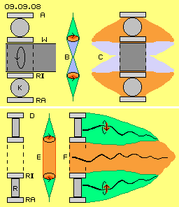
At picture 09.09.08 upside that ball-bearing is drawn once more, at A and C by longitudinal views. Inside of the inside-ring (RI) a shaft (W, dark-grey) is drawn (corresponding to normal function of a ball-bearing). From the outside-ring (RA) via the balls (K) to the inside-ring (RI), the turning-speeds are increasing (like generally at potential vortices). Opposite the atoms of the shaft are moving slower from outside inward (like at every rigid vortex). At this picture upside at the middle at B, the extension of the motion-intensity is marked by green cones. Towards the centre, the motions become slower, like marked by the blue cones.
These motions must be balanced towards the Free Aether. That aura aside of the ball-bearing is schematic drawn upside right at C. From the stationary outside-ring further inward, the balancing-area reaches further out into the space (marked red). From the inside-ring inward, less balancing-area is necessary (marked blue). This is the common vortex-pattern of all whirlpools, e.g. also of the earth: from the border of the earthly aether-vortex (radius about one million kilometer) further inward, the stroke component becomes stronger, e.g. pushing the moon forward by about 1 km/s. At height of geostationary satellites the drift is about 3 km/s fast. The ´rigid´ earth decelerates the vortex, so from earth-surface inward the absolute turning speed is linear reduced.
Central-Vortex of Ballbearing
At the longitudinal cross-sectional view at F, the green faces mark the area of charge, here represented by manifold wounded black connecting-lines (here is drawn only the right side, left side would be analogue). The charge-layer aside reaches far out into the space. These movements will not end exact at the inner border of the inside-ring. That clear motion-pattern can spread unhindered into the central area, like marked by the red area. There the aether moves corresponding to the aether of an electrostatic charge. As an additional overlay there exists also the motion-pattern of that ´bow-shaped stroke´ which resulted from the mechanic motions of the ball-bearing.
Oversize Speed
Acceleration by Aether-Pressure
The more intensive that ´increased charge-swinging´ becomes, the further outward reaches the aura aside into axial direction. The surface of the aura increases, so the Free Aether can affect stronger counter-pressure, like below right side at F is marked by the horizontal blue arrows. The general aether-pressure can compress these movements into longitudinal direction, however can not stop these intensive motions. That motion-pattern become only corresponding wider, like marked by the vertical light arrows. So that central motion-pattern is shifted into areas of inside-ring and the wheels. That pattern of compressed strokes represents high revolution-speed. In comparison, the ´material particles´ are turning too slow. The inside-ring and the wheels are affected by additional thrust, i.e. they become accelerated until they correspond with that stronger drift-speed. The revolutions of the ball-bearing are accelerated, thus demanding extended aura aside. The faster turning inside-ring results stronger stroke-sectors. These spread into the centre and produce stronger pressure into axial direction. The counter-pressure of Free Aether again results a new phase of previous acceleration-process.
Normal and disastrous
The movements of that face become wider, e.g. like marked by the face left side at C. The aether-points do longer ways at tracks more stretched - however they do not fly faster. The short track-sections of the Free Aether are only some ´unravelled´ (e.g. like chaotic molecular motion of gas-particles are transferred into an ordered flow). The aether-points move by unchanged speed only at some straighter tracks.
At this surface at C, also a stroke-component (dark-red sector) is sketched. This comes up inevitably e.g. when two circled motions are overlaying. At the one hand the track is stretched (and the aether-point is passing faster this sector), same time however an other sector is condensed (and the aether-point is moving slower). As a whole all movements occur with the average of the general speed (of light or some faster). Even all aether is one coherent whole, multiple local motion-pattern are possible. Mostly they come up by that ´cone-like´ extensions and these ´stroke-components´.
At this picture right side at the middle at D, a situation is sketched where two neighbouring aether-areas are turning with different speeds. The blue lines point out, how connecting-lines become ´twisted´. Within the gapless aether comes up stress respective it´s finally impossible that neighbouring aether-points are mutually passing by. The aether-vortices of material particles well can fly different directions nearby each other, e.g. when two wheels side-by-side are rotating with different speeds. Within the gapless aether however, neighbouring aether-points must keep neighboured directly and all times. Thus an disastrous stress comes up, when previous ´oversized´ turning comes up at the centre of the ball-bearing vortex. This speed no longer corresponds to the average speed of movements of Free Aether. That whirlpool no longer shows the necessary asymmetry. Practically no balancing movements are possible to reduce the differences. The result is really a catastrophe - for such ball-bearing machines - or even for a star.
Excursus: Pulsar
However, previous consideration could explain these appearances respective a pulsar is a gigantic example for these processes. The gas-particles of a star are compressed by the outside general aether-pressure (and not by mass-attraction). The particles collide frequently and hard collisions result previous ´twisting´ of connecting-lines. These stress-situations produce radiations, hitting next particles with their light-speed, so that gas-area is heated-up extremely. Finally the aether can handle the strong tensions only by a general ´liberation-stroke´: the star explodes in shape of a super-nova.
The outside shells of the star are pushed off, sometimes rather concentric, e.g. like this picture 09.09.10 shows. Then, also the counter-pressure of the explosion affects radial concentric inward. The gas-particles become concentrated and their vortices probably could pass over to a plasma. At the shell-shaped focus of the explosion still exists a stroke-component, corresponding to the rotation-speed there. The radius will be some hundred thousand kilometer and one revolution will take some days. If now these stroke-components are shifted concentric inward by the concentric acting explosion-pressure, these ´oversized´ turning speeds come up (what´s the real process for the theoretic constant of mechanic turning-momentum). At the radius of few kilometer thus can result diverse revolutions each second. At the pole-regions generally exist slower movements - and through these ´weak-spots´ finally the ´over-stressed´ aether can slacken - by pushing off jets with supra-light-speed.
Controlled System
Based on this understanding, one should be able to control these processes. At the one hand, a mechanic turning momentum is achieved, i.e. these machines could work as motors. At the other hand, the original static charge is enforced by these processes, so machines could also work as electric generators. Next chapter ´ball-bearing aether-machines´ will show some proposals for realization of that principle.
At previous chapter was mentioned, unipolar-machines are driven also as an ´eddy-current-brake´ to generate extreme strong current impulses. For example, these are used for ´rail-guns´ to accelerate missiles up to ultrasound speed. The general principle is sketched at picture 09.09.01. The projectile (P, green) is build by electric conducting material and rolls or glides at two parallel rails (R, black). A current (many amperes strong) is fed into one rail. The current flows along the projectile and back again via the second rail, as marked by red arrows from minus to plus. The projectile is accelerated extremely into direction of the green arrow.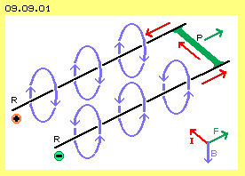 The common explanation here is also sketched. Around the rails comes up a strong magnetic field, each left-turning in direction of the current, as marked by the blue circle-arrows. The projectile practically is a conductor for the current, crossing the magnetic fieldlines right-angles. So the projectile is affected by Lorentz-force, again by right-angles. Right side below the common hand-rule is drawn (here based on physical direction of current, thus left/right-changed). The magnetic field (B, blue) shows down, the current (I, red) flows through the projectile towards left-upside, the resulting force (F, green) shows upward-right.
As this linear acceleration functions, also accelerated rotation should be possible. Diverse explorers thus experimented with ´ball-bearing-machines´. The general principle is shown at picture 09.09.02 upside left at A by cross-sectional view and upside right at B by longitudinal view. Previous rails practically are bended to rings. The outside ring (RA) is fed by voltage. Via glide-contact at the inner ring (RI) respective at the shaft (dark grey) the current flows back to the source. Between both rings some balls (K, dark grey) are running around, building the electric connection. Also this motor functions, even its construction is merely mentioned at textbooks. Obviously one welcomes, that "the efficiency is rather small" and thus there is no demand for explaining the working effects. Opposite, some researchers achieved most surprising results.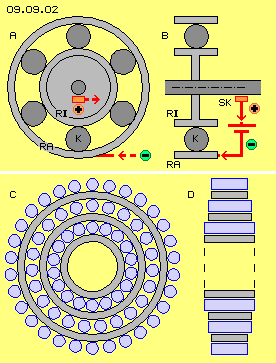 Magnet-Machines
Strong swirls within the aether are also achieved, when permanent magnets rotate. Well known e.g. are manifold experiments of John Searl. The general conception is sketched at picture 09.09.02 below, left at C schematic by cross-sectional view and right at D by longitudinal cross-sectional view. In principle were used several rings (light grey) which can be stationary or turning. Between or around the rings, some cylindrical ´runners´ (blue) are installed, which are turning around the system axis and their own axis same time (practically rolling along the rings). All constructional elements are build as permanent magnets, partly by multiple layers with complex structure and polarization into differing directions.
Based on these and other experiments one can state one fact without doubts: there are not only pure mechanic motions, there are not only interactions between magnetic and electric fields, but the decisive effects can only occur within the real substance of surrounding aether. One must go back to the most simple arrangements for analysing the process. Therefore two known experiments schematic are drawn at picture 09.09.03. A view top-down is shown at A, a cross-sectional-view at B and a side-view at C. At two rails (light grey) rests a round cylinder, build by two permanent magnets. It´s told the experiment will function only if both south-poles (S, red) meet at the middle and the north-poles (N, blue) are showing outward. If a DC is fed into one rail, the currents flows along the iron-cylinder and via the second rail back to the source.
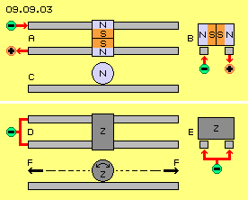 Below at this picture 09.09.03 now the most simple arrangement is drawn, at D by view top-down, at E by cross-sectional view and at F by side-view. Voltage is put on both rails (and few volts will do). A round iron- (or steel-) cylinder (Z, dark grey) lays on both rails, building an electric connection. The whole system is connected only with the minus-pole of a (DC-) electric source. There is no connection to a plus-pole or to the ground. So no flow is running, but the rails and the cylinder are only ´static charged´. If now the cylinder is started to roll, it goes on rolling and accelerates by itself. One can start the cylinder to turn left or also towards right side - into both directions it will roll further on and accelerate automatic (see both arrows F). At the internet one can read meagre statements like this: "a static charged cylinder shows a turning momentum into direction of its movement" - an explanation ´why´ one will merely find - because impossible by conventional understanding.
At picture 09.09.04 upside, this experiment is shown once more, again by view top-down (A), cross-sectional view (B) and side-view (C). As no current is running, one rail (S, light grey) will do. The round (iron-) cylinder (Z, dark grey) might be suitable at its best with an oval cross-section at its long axis. Voltage is put onto the conductive rail, so all around its surface exists electric charge. That static charge will also cover the electric conductive cylinder.
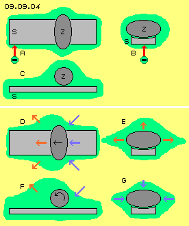 At D, the cylinder was pushed softly, so it starts to roll to left side. This mechanic motion affects additional aether-movements, so the aura around the cylinder is some enlarged. At the cross-sectional view at E, the green marked areas show that expansion upside and at both sides. The red arrows show the direction of that widening. Even these constructional elements are conductive, the charge ´keeps static´ at the surfaces (see also below). As the cylinder is turning, also its charge comes into a turning respective forward-directed motion. The ´charge-hill´ of the cylinder is pushed upside over the charge-layer of the rail. At the side-view, the red arrows F show, how the green area of charge-movements is piled up in front of the cylinder.
An electric generator (the usual units or of previous chapters) pile-up strong charge onto a conductive surface (building a potential respective ´tension´ versus areas of less charge). Finally by a second step the flow of electric current comes up (because the general aether-pressure pushes the charge-layers down to likely height at all surfaces). So generally is valid the rule: ´the electric current chronological follows the voltage´. For example, at 50-Hz-AC the current follows with a delay of 90 degree of the phase, thus about 0.005 s later.
The electromagnetic waves are racing through the space by speed of light, from and into all directions, thus crossing everywhere any time. The movements of Free Aether are a mixture of these overlays. It´s ´trembling´ respective it´s running at ´chaotic tracks´ within narrow space, nevertheless all times by speed of light with some 300000 km/s. A ´material body´ can move only slow through that ´stationary´ aether, as the complex vortices of the atoms are forwarded into drive-direction. Still e.g. the earth wanders with about 40 km/s around the sun and whole sun-system travels around the galactic centre up to 260 km/s. So the earth is moving by remarkable 300 km/s through the space - nevertheless 1000 times slower than the internal aether movements.
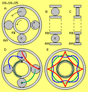 At the following are discussed the effects, which can come up at rotating systems. At picture 09.09.05 upside left at A the cross-sectional view shows an outside- and an inside-ring (RA and RI, light-grey) and some balls (K, dark-grey) between. The outside-ring is stationary, the balls are right-turning around their own axis. They are rolling left-turning around the system-axis and thus are shifting the inside-ring by double revolutions around the system axis (see arrows), like it´s normal function of a ball-bearing. Upside at the middle at B is sketched a corresponding longitudinal cross-sectional view.
A ballbearing is a ´round stuff´. However on closer inspection, there are not only pure circling motions. Below left at D some mass-points are marked at the wheels and their tracks are shown by curves. One point at the centre of the wheel below is marked light-green and that point is really moving at a circled track (light-green) around the system axis. A point at the rim of the wheel at left side is marked red and that point is ´jumping´: at first it becomes faster running inward-forward, some later it´s guided outward and slowed down, finally nearby standing still for a short moment. All mass-points at the rim of a wheel ´bounce´ around the system axis at that curve marked red (like e.g. all mass-points of a tire are jumping forward by such bows over a plane street).
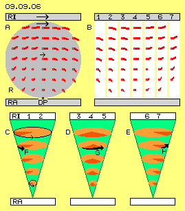 Nevertheless exists a common and clear motion-pattern, which is shown at picture 09.09.06 at A by side-view. Between the outside- and inside-ring (RA and RI, light-grey) is rolling a wheel (R, dark-grey) towards right side. At this wheel are marked many points and red lines indicate the direction they are moving momentary. In addition, the lengths of the lines indicate the momentary speed. All points of left side are moving upward, some later into horizontal direction and finally right side down. Below, the inclination is strong and upside, the inclination becomes flat. The speed of point upside is generally faster than the speed of points below. All points momentary are moving as if they would swing at a bow around the suspension-point (marked as fulcrum DP) of the wheel at the outside-ring.
When atoms are moving continuously at likely tracks, the aether will not come back to its original movement completely. The atoms leave a ´trace´, here in shape of that ´bow-shaped stroke´. As all aether is coherent, also the neighbouring Free Aether becomes ´resonant´ swinging, at least when a clear motion-pattern exists. At this picture below at C is sketched a typical cone, representing the motion of a connecting line. At level of the stationary ring (RA) the aether ´trembles´ at narrow space. Towards the inside-ring (RI) the mechanic motions are faster and at corresponding wider tracks also the aether will swing. This cone is drawn once more at D and at E.
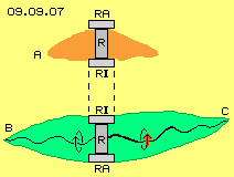 Like mentioned upside with the relations of speeds, that co-swinging represents only millionth parts of the average movement of Free Aether. Nevertheless this represents an additional motion, demanding corresponding wider area for balancing movements. At picture 09.09.07 at A thus left and right side of that wheel (R, dark-grey) is marked a light-red ´aura´. This will be small near the stationary outside-ring (RA, light-grey) and will reach further out near the fast turning inside-ring (RI, light-grey). As a whole however the normal trembling of Free Aether is changed only little bit.
Wide-range movements within the gapless aether can only come up by extension of narrow tracks. The radius of swinging motions become longer and the track of the connecting-lines build a cone. As a rule, the swinging is unequal based on overlaying motions, which inevitably result stroke-components. These strokes e.g. drive the vortex-complexes of ´material particles´ forward within the aether-space. Every motion must be balanced within a local area same time. For example, the swinging of an electron all around is ´time-shifted´, e.g. like discussed by the ´clocks´ at picture 09.03.03 of previous chapter.
 Also the aether-movements of that mechanic ball-bearing can only result by extension of swing-radius (in shape of cone-tracks of connecting-lines) and overlaying motions (here especially of the charge-pattern). In addition, the movements of the atoms result a stroke-component within neighbouring aether (or opposite, they drift within these aether-movements or they are pushed forward by these strokes). And all involved aether-volumes must move adequate all around, so finally all motions mutually compensate each other.
If at the centre of the ball-bearing exists no massive rigid body, an other vortex-structure will come up. At the picture below at D an extreme case is sketched, where the area inside of the inside-ring (RI) is completely empty. So no necessity for reduction of motion-intensity exists at the aether there. At E is marked by the red area, that the extension and stroke-component of aether-movements can reach unchanged through that central area.
At picture 09.09.09 upside left at A, a cross-sectional view of the ball-bearing is drawn. Between outside- and inside-ring (RA and RI) are arranged eight wheels (R). Below at this cross-sectional view the increasing motion-intensity from outside inward is marked by the green cone. The lengths of the red lines indicate the speed respective strength of the stroke-component. All rolling wheels all around result that ´bow-shaped stroke´ within the neighbouring aether aside. The sectors of strokes are drawn at the inside-ring all around. That motion of aether corresponds to the high revolution speed of the inside-ring.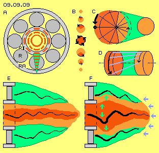 Within the central area, the aether can behave likely. The sectors of strokes come closer to each other and finally, within the narrow space of the centre, they build a closed circle (see red bow-shaped curves and central red ring). At the picture upside at the middle at B, the extension of motions are sketched by round faces. The outside-ring is stationary and the small red face represents only the narrow ´trembling´ of Free Aether. Further inward, the aether-movements become wider and a sector of fast motion comes up (the stroke-component, dark-red) plus a sector of slower movement (for balancing, light-red). At the inside-ring, the sector of stroke is most wide.
As now that motion-pattern is not hindered to spread into the central area, the fast motions of strokes follow directly one by next, here marked by the dark-red face and four black arrows. The aether at the centre is ´turning´ faster, because it´s motion exists only by stroke-components. At this picture below left at the longitudinal view at E, that central area of ´oversize´ aether-motions is marked by dark-red face. Like this, the aether inside of the inside-ring behaves. Aside of, the charge (light-green) reaches far out into the space. Within that clear motion-pattern these additional stroke-components (light red) unhindered can spread further inward. At the centre the swinging of the charge is complemented by the intensive strokes (dark red) to an ´oversize´ frequency.
At this picture 09.09.09 upside right at C schematic is sketched once more, how an extension of aether-movements works. The light-red circle right side represents an area of Free Aether. There many motions swirl to and fro and all over that spot, e.g. as a result of numberless overlays of all crossing radiations. These movements at short tracks are running by speed of light (or some faster, because the light represents only the speed of the signal, the medium by itself might run faster, e.g. the air-particles are moving 1.4 faster than the sound progresses).
 The astronomy deals with 5 % of the universe and puts 95 % into a black-box called ´dark-matter or dark-energy´. So it´s rather dubious to calculate back in time for millions of years up to a suggested big-bang, in addition assuming universe-wide constant of ´mass-attraction´ and same time constant and maximum speed of light. So it seems rather unreliable to believe, e.g. triple sun-masses could collapse to a neutron-star of 20 km diameter and such pulsars could do one revolution during few seconds or even a hundredth second and push off ´jets´ into axial direction, millions of kilometer - and beyond speed of light.
Some experiments obviously reproduced these disastrous situations. Reports are often talking about step-wise self-acceleration. At previous discussion these processes were based on electrostatic charge of systems. Analogue could react the systems based on rotating permanent magnets. In principle, at first is necessary an ordered aether-swinging (here of a charge, there of manifold magnetic fieldlines), ´heated-up´ by overlaying movements (e.g. by revolutions around system-axis and additional revolutions around own axis). At the one hand, these pulsating respective amplified movements are a result of the rotating mechanic parts and ´static´ fields, which makes the neighbouring Free Aether resonant co-swinging. At the other hand, the enforced strokes within the aether affect thrust on the material parts of the machine.
09.10. Ballbearing-Motor/Generator
09. Aether-Electro-Technics