07.05. Centrifugal-Thrust-Engine
(download print version ap0705e.pdf 228 KB, 17 pages)
Objectives
Several different versions of air-drive engines have been described in the previous chapters. One which is particularly powerful, is the ´Suction-Cylinder-Engine´ when driven by compressed air. Water-drive engines require a much more complex organization of closed circuits due to the strong centrifugal forces caused by using such a dense working-medium.
This new conception of ´Centrifugal-Thrust-Engine´ will show, centrifugal forces can contribute to turning momentum. Initially, however, we need to discuss some general points of view concerning the inertia of rotating systems.
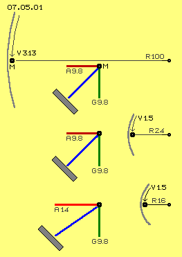 Gravity- and Centrifugal-Forces
Starting point is a mass (a sphere or water) moving at circular path around the inside wall of a hollow cylinder. Centrifugal forces affect all times radial outward. Gravity affects all times straight downward. Picture 07.05.01 shows graphs of three situations.
Upside of picture partial is shown cylinder (grey) with radius of 100 cm (R 100). Along its inner wall, mass M (black point) is moving at a speed of 3.13 m/s (see arrow V 3.13). This mass is continuously is redirected inward by the cylinder. Centripetal acceleration is calculated by the formula speed squared divided by radius, in this case, with 3.13 m/s at a radius of 1 m results acceleration A = 3.13^2 / 1 = 9.8 m/s^2.
Corresponding to that acceleration towards centre, centrifugal force of that mass affects outwards. That centrifugal force (A 9.8) is drawn as the red vector at the graph. Gravity acceleration is also about 9.8 m/s^2, here drawn as green vector (G 9.8) vertical-downward. The resulting force is marked by blue line. If previous cylinder-wall were replaced by the inside surface of a cone (grey) with a 45 degree inclination, then this mass would rotate by the same speed, maintaining a constant height.
At middle row of that picture, radius of wall is only 24 cm (R 24) and mass moves only by 1.5 m/s (V 1.5). Centripetal acceleration thus is A = 1.5^2 / 0.24 = 9.8 m/s^2, so here again the centrifugal force (A 9.8) corresponds to the gravity acceleration (G 9.8). Force diagram thus matches previous graph.
Same speed of 1.5 m/s (V 1.5) however at shorter radius of e.g. 16 cm (R 16) produces stronger centripetal acceleration of A = 1.5^2/0.16 = about 14 m/s^2 (see lowest section of picture 07.05.01). As force diagram shows, mass at round track (grey) along wall of 45 degree inclination is pushed upward, like commonly know, e.g. by stirring coffee.
Lifting-Force
 At picture 07.05.02 previous situations at radius 24 cm and 16 cm (R 24 and R 16) once more are drawn by larger scale, now however the masses are moving at the higher rate of 6 m/s (V 6). Centripetal acceleration is corresponding stronger with A = 6^2/0.24 = about 150 m/s^2 respective A = 6^2/0.16 = about 225 m/s^2 (A 150 and A 225).
In both of these cases thus centrifugal force is essentially stronger than gravity force (green short vertical vector G 9.8) and so the resulting net forces (blue vectors) are much closer to the horizontal than before. These masses will therefore rotate at a constant height when moving alongside much steeper walls (grey) of hollow cone.
At picture downside is sketched situation where these forces affect onto wall (grey) some less steep. A wall takes pressure right angles to its surface (dark green vectors), so resulting are force-vectors showing upward, parallel to wall (H 20 resp. H 30). Depending on the speed and the inclination of the wall results acceleration of mass parallel upward along wall, at this example by range of about 20 to 30 m/s^2. The faster the stirring and the more flat cups resp. plates are, the more coffee or soup spill over. Part of centrifugal force becomes force-component opposite to gravity. In this example, already the speed of 6 m/s resp. six revolutions / second resp. 360 rpm produces a lifting-force much stronger than the gravity-force.
Spiral Tracks
At picture 07.05.03 left side schematic is shown a sphere A, e.g. bowling ball, rolling straight towards left at a flat horizontal surface. Downside of, analogue track is shown, however at circle alongside inner wall of hollow cylinder. If a ball (or also water) enters that pipe by certain angle E, it rolls at spiral track until upper end and exits by likely angle F. Track thus shows continuous likely inclination, practically like any screw thread.
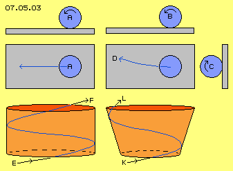 At this picture right side once more bowling ball B is sketched, again rolling at plane towards left. Now however that ball got overlaid additional turning movement C, cross to its forward movement. Bended track D results (like any bowling-fan perfectly demonstrates).
Corresponding to that cross-force C affects previous lifting-force H, if that ball (or also water) enters downside into an conical funnel. Track does not run by likely inclination upward, but increasingly is directed upward-outward. Mass won´t go on with original angle K, but will move at path more steep and exits by angle L more acute.
Steeper and shorter and faster
At picture 07.05.04 the jacket of previous cone (light red area, opened out to form flat surface) is sketched, where cross-lines indicate each 30 degree strip of conical surface. Water flows into downside border of cone at A and some 150 degrees later (sector S 150) exits at upside border at B by likely angle of 30 degrees. That spiral path C (blue) thus represents steady inclination. So this track is only theoretic, because centrifugal forces are not included.
Within cones however, part-component of centrifugal force acts parallel to wall. Resulting path inclusive that lifting force is sketched at D. Water also enters by 30 degrees at downside border, however exits upside border by steeper angle of about 35 degrees. That track D runs within sector (S 120) which spans only 120 degrees, thus this path is shorter and steeper and thus also is done faster than previous track C.
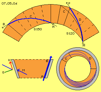 At this picture downside right hand, view from upside down onto that hollow cone-trunk is sketched. Track C with its rate of rise is drawn and also that steeper and shorter track D. Downside is marked by diverse curves, how water moves fan-like alongside inner wall, moving ´screw-like´ upward, however by increasing inclination.
Downside left at this picture schematic is sketched cross-sectional view onto that cone-like cylinder. Water in general enters downside, moves alongside inner wall and exits upside.
Diagonal movement M schematic is drawn once more left side. Inertia all times shows straight ahead in movement direction, here thus diagonal-ahead towards inner wall. Redirection of flow results centripetal acceleration resp. centrifugal forces onto inner wall. That wall can take force G only right angles to its surface, so force-component H results, parallel to wall, much stronger than at upside example of rotation at steady height.
Up to now at this first section, only known facts were mentioned. At conception of this Centrifugal-Thrust-Engine that hollow cylinder in shape of cone-trunk is ´passive element´. Alongside its stationary inner wall working medium (water or oil) flows. Corresponding ´active´ element is an also conical cylinder. Its properties now are discussed at following second section, at first again by some theoretic considerations.
Rotor-Cylinder
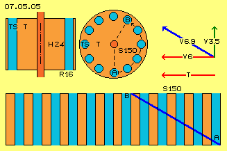 At picture 07.05.05 that turbine T (red) at first however simplistic is drawn as round cylinder, upside left by longitudinal view, aside by cross-sectional view and downside by view from outside (or surface opened out). At radius of 16 cm (R 16) resp. at circumference of 1 m round canals are arranged, here marked as turbine-blades TS (light blue). Here e.g. twelve of these canals are sketched, each parallel to system axis and running straight line from bottom to top.
Water downside turns e.g. by 6 m/s just as fast as turbine (see arrows V 6 and T). Water e.g. enters by angle of 30 degrees upward into canals. Vertical speed thus is about 3.5 m/s (green arrow V 3.5), diagonal speed thus is about 6.9 m/s (blue arrow V 6.9).
Due to rotation of cylinder drum, water within canals actually flows at spiral track diagonal upward, like here sketched at circumference by blue line from A to B. If height of cylinder is e.g. 24 cm ( H 24), then water moves within sector of 150 degrees (S 150) during its upward flow.
Rotor-Cone
At picture 07.05.06 upside left now turbine T (red) is drawn as conical cylinder. Canals at downside inlet again are arranged at radius 16 cm (R 16), at upside outlet however at radius of 24 cm (R 24). These turbine-blades TS (light blue) thus show diagonal upward-outward from downside inlet to upside outlet.
Like at previous picture, water again will enter diagonal by angle of 30 degrees (now however parallel to diagonal wall). Height of cylinder is that kind, length into diagonal direction again is 24 cm. Path of water within space thus corresponds to previous track from A to B of previous picture, thus again spanning a sector of 150 degrees (S 150).
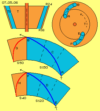 At picture 07.05.06 middle row, now shows jacket of that cone-trunk resp. its surface laid out flat. That track C (dark blue curve) now runs spiral upward and outward from A to B, within that sector marked blue (S 150). Since circumference at outlet is longer than at inlet (in ratio of radius 16 to 24 cm), outlet within space moves by faster absolute-speed than water moves. Thus water within canals would be accelerated (what´s not job of any turbine).
So water can follow canals by its given speed, theses canals need to be curved backward in turning sense of system. Canals must show curved line within sector of 50 degrees (S 50, marked red) like sketched by curve G (dark red).
As stated upside, water within these canals naturally press also at outer walls, due to centrifugal forces. Starting at certain speed, thus also these water masses become lifted upward. If canals allow that additional motion upward-outward, water upside will flow off outlet by angle more acute.
This is shown at downside section of picture. Water downside enters by angle E of 30 degrees, however exits outlet by angle F of 35 degrees. Water flows at shorter and steeper path D, which spans a sector of only 120 degrees (S 120, marked blue). Within that shorter time, outlet turns less within space, so canals can be arranged some steeper, like sketched by track H (dark red) within sector of only 40 degrees (S 40, marked light red).
At this picture upside-right schematic is sketched cross-sectional view through that cone-trunk resp. view top-down onto system axis. Upside canal G (light blue) is drawn, curved backward (in turning sense of system) within a sector of 50 degrees. Water flows within that canal from inlet A to outlet B, while moving within space by 150 degrees. Downside canal H is shown with its backward-curve spanning a sector of only 40 degrees. Water within that canal flows from E to F and forward within space only 120 degrees. Based on its centrifugal forces, that water flows some faster and reaches outlet some earlier.
Turbine-Blades
At picture 07.05.07 left hand once more that ´neutral´ track H (dark red) of canal within sector of 40 degrees (S 40, light red) is drawn and corresponding steep path D (dark blue) of water, moving within a sector of 120 degrees (S 120 light blue). Left hand at upper part, view radial onto system axis is shown, left hand downside curved canal H and steep path D are drawn at jacket of cone-trunk.
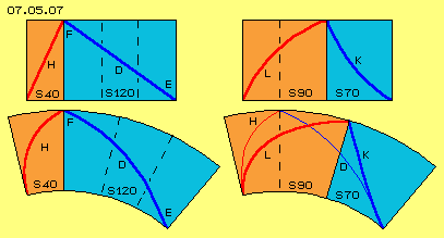 If now water shall not move ´force-neutral´ through that cone-trunk but shall generate mechanic turning momentum, canal must be curved further backward in turning sense, like at this picture right side schematic is shown. Here for example, curve of canal is stronger bent by additional 50 degrees, like marked by curve L (dark red) which now spans sector of 90 degrees (S 90, light red, previous 40 + 50 degrees).
Correspondingly, now path K (dark blue) of water within space is pressed sharply upward. Water moves within a sector of only 70 degrees (S 70, light blue, previous 120 - 50 degrees). Right hand upside, again that´s shown by radial view onto system axis, right hand downside at jacket of cone-trunk. ´Neutral´ curve H of canal resp. ´neutral´ track D of water again are marked by thin lines. In comparison now redirection of water at that shorter and steeper track K becomes obvious.
Also at that second section, only known points of view for turbine with axial throughput were mentioned. For ´normal´ conditions, that conception is not really good. If however previous discussed facts are combined with following new constructional elements, special and most effective functions of that machine are achieved.
Cone-Wall and Cone-Turbine
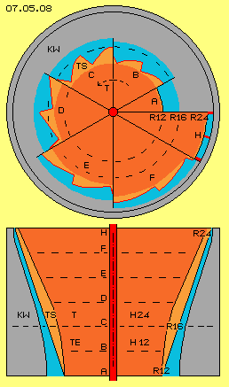
At picture 07.05.08 downside longitudinal cross-sectional view of turbine T (red) is drawn, which upside e.g. has radius of 24 cm (R 24) and downside of 16 cm (R 16) and height of about 24 cm (H 24). Below the main conical turbine (below dotted line) is an additional area of turbine-inlet TE with a height of 12 cm (H 12), which tapers down to a radius of 12 cm (R 12).
At previous theoretic example, general arrangement of turbine-blades TS (light red) were discussed by round canals within turbine. Now here at real machine, canals are arranged at side-surface of turbine and canals are open towards outside. Total turbine-cone fits into cone-wall KW (grey). This wall is fix connected with housing (here not drawn) and within that housing-hollow-cone now is turning that turbine-cone-trunk.
Water (light blue) fills the space between surfaces of both constructional elements, at the one hand as ring-shaped water-masses alongside cone-wall and at the other hand as water-masses within turbine-blades.
 Sawtooth-Blades
Mechanic turning momentum is generated by flows only by pressure onto pressure-sides of turbine-blades. At common turbines, each two neighbouring blades build canals, where frontside (in turning sense) face of wall represents pressure-side and backside face of wall represents suction-side. Torque is based on pressure-difference at both faces of walls. That difference becomes maximum, if there is no suction-side at all. This is possible along surface of that cone-shaped turbine in shape of sawtooth-like contours.
Here, these turbine-blades have a pressure-side which (nearby) shows into radial direction, corresponding to frontside wall of canal. Here, canal has a ´bottom´ resp. an inner-side which (nearby) shows in tangential direction. Diagonal-outward-upward moving flow practically moves parallel to that inner side. Pressure-side plus inner-side build contours of an asymmetric sawtooth. Each inner-side extends from inner edge of pressure-side to outer edge of following pressure-side. That triangle contours thus has no backside wall resp. suction-side.
At longitudinal cross-sectional view are marked diverse axial levels by dotted lines A to H. Upside at picture 07.05.08 these cross-sections are partly drawn, each by a sector, one level aside next level. At downside end A of turbine-inlet, radius is 12 cm and ring-shaped cross-sectional surface is available for water between round turbine and round cone-wall (here drawn within a sector of 30 degrees).
Further upward, tooth-shaped blades extend further out of the surface of turbine-cone. At B, inner edge still is nearby radius 12 cm, while outer edge reaches further out into ring-shaped canal. Here for example are assumed twelve turbine-blades, at sector B of 60 degrees are drawn two of these ´saw-teeth´.
Level C marks the junction between turbine-inlet area (TE) to the main body of the turbine (T). Teeth there reach to radius 16 cm and at the other hand, notches are most deep. At that sector C of 60 degrees again two of these teeth TS are drawn.
Further upward resp. outward, circumference becomes longer and thus also notches become longer. If the cross-sectional area for water were to remain constant, then the notches need to be corresponding less deep. At these sections D, E and F are drawn each two turbine-blades within sectors of each 60 degrees.
Sector H is shown only by 30 degrees, so length of one tooth. At this radius of 24 cm begins area of turbine-outlet, where water should exit by most homogenous flat jet. Consequently, the contours of canals should be ring-shaped. Also water previous running alongside cone-wall resp. outside of canals, now could be integrated into canals. Surfaces there could build a nozzle and these long-stretched canals well could be divided by additional walls (thick red lines), so pressure-surfaces are enlarged at this area.
Winding Staircase
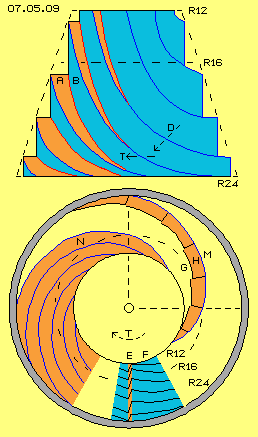 Picture 07.05.09 attempts to give the impression of the spiral arrangement of previous tooth-shaped notches running around the surface of cone-trunk: at cone-like mountain are ways A (red) all around, downside beginning flat and becoming upward increasing steeper. Each way is bordered by vertical wall B (light blue), upside of which next way is arranged. Only at left hand side of mountain ways are visible, while at right hand side only these vertical walls are visible.
Generally here rotation is assumed left-turning. As here that cone is drawn upside down, ways go up right-turning. If that hill is assumed to be a turbine, water flow D is directed diagonal downwards clock-wise, hits nearby right-angles onto these ways and results turning of turbine T (see arrows).
At this picture downside, view top down onto that cone-like hill is drawn. Quite downside at E and F are marked lines of likely height, showing tooth-shaped indentations into surface. Into turning sense, that edge E (red) represents pressure-side, while other (inner) side F (light blue) represents only slope surface and thus no ´suction-side´ exists.
Now these indentations are not arranged straight down but are shifted like sketched at G. Previous vertical indentation E now create the pressure-wall H (red), practical corresponding to previous way A with its spiral curved track. Previous inner-walls F now are arranged one besides next and thus building surface M (blue) respective previous vertical walls B between ways. In effect, whole hill is build from these successive ´winding staircases´, however which actually don´t have any stairs. These faces spiral upwards by progressively smaller radius and increasing steepness.
At N is drawn part with several of these spiral ways, where vertical walls between are visible only as small blue curves. If again that hill is assumed to be a turbine, total surface of that cone-trunk is a pressure-side in shape of these spiral surfaces all around. Like diagonal falling rain, water flows all around down at surfaces of that hill, anywhere right-turning and thus generating rotation of that turbine. At this machine, that turbine-cone is surrounded by cone-wall (here not drawn) and water flows between cone-wall and turbine like previous rain.
Crossing Flows
At picture 07.05.10 jacket of cone-trunk is shown by its total 360 degrees surface, four times one below the other. Wide part of cone-trunk has a radius of 24 cm and a circumference of about 150 cm (R 24 and U 150), narrow part has a radius of 16 cm and a circumference of about 100 cm (R16 and U 100), the length of side-surface is about 24 cm (H 24). By example of these dimensions, flows upside were discussed alongside cone-wall and within turbine-canals.
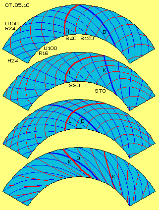 Entrance of water at narrow circumference was assumed by acute angle of 30 degrees. If moving by steady angle, flow would run within a sector of about 150 degrees and exit by likely angle. Based on centrifugal forces, water however is lifted at cone-wall, takes track more steep within a sector of only about 120 degrees (S 120) and exits by angle of about 35 degrees. That path D (dark blue) is marked at jacket upside of picture several times.
Also water within canals would take corresponding track. However water can not follow faster moving wide circumference upside of cone. In order to achieve ´force-neutral´ track, canals should be bended backward in turning sense by one third. That canal H (red) within sector of 40 degrees (S 40) upside at picture is also drawn several times.
As turbine is intended to generate mechanic turning momentum, canals must be curved further backward. Here for example that sector was enlarged to 90 degrees (S 90) so water is guided faster outward within a sector of only 70 degrees (S 70). At second jacket that strong cueved canal L (red) and corresponding steep path K (blue) of water within that canal is drawn several times.
Canals of turbine here are represented by tooth-like notches, thus are open towards outside. So alongside turbine-surface meet two flows: at the one hand forced movement within canals and at the other hand free flow of water alongside cone-wall. At third jacket of that picture again these canals L (red) are drawn several times and now also tracks D (blue) of free flowing water. Both cross about right-angles.
Free flowing water upside is too slow for turbine-surface there moving rather fast, however water is still fast enough to flow cross over backward curved canals L. At jacket quite downside of picture, both different flows are drawn: track D (blue) of free flowing water and forced track K (here now marked red) of water within canals.
Both flows here again are drawn several times and that kind, crossing becomes obvious: free flows cut tracks of water within canals by acute angle, all times from backside into forward direction. Free water ´brushes´ water within canals, forward in turning sense of system. So water within canals becomes revolving.
Water within canals became redirected backward and did transfer its inertia onto canal-pressure-sides and thus its forward-motion got decelerated (like torque is produced by any turbine). That water still shows centrifugal forces, however the more outward that water wanders, the faster pressure-sides run off ahead. That water ´too-slow´ could affect pressure only at walls curved backward much stronger, however only by small angle and thus with practically no additional turning momentum.
Also free-flowing water can not follow fast movement of turbine at its wide circumference. However that water well flows fast enough forward-outward to put water within canals into additional turning around longitudinal axis of canals. That revolving-water-cylinder practically works like gear (of gear-wheels with axis not parallel) and transfers flow-pressure of free-flowing water onto pressure-sides of canals. Water alongside cone-wall is not pressed into canals by itself and thus is not redirected and its forward-motion is not decelerated. So centrifugal forces of that free flow can go on contributing to turning momentum of turbine, however only indirect by driving that water-cylinder within canals.
Revolution within Canal
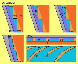 Picture 07.05.11 shows parts of area between the cone-wall KW (grey) and the turbine T (red). Free flowing water moves alongside cone-wall upward-outward. At surface of turbine, turbine-blades TS (light red) are arranged in shape of tooth-like notches. Water within these canals is guided outward by steeper track. Turning momentum is generated by redirection of these parts of water.
At pressure-sides of these canals, in addition weights flow-pressure B of free flowing water. These parts of water flow at path less steep and thus move faster in turning sense of system, i.e. sweep over canals. Within canals thus comes up spinning movement C, increasing pressure onto pressure-sides of canals. So also these free-flowing parts of water indirectly contribute to turning momentum.
Downside-left of picture, upper outlet of the turbine is sketched. There also that free-flowing part of water should be guided into canals, e.g. as cone-wall is bent some inward. Also that part of water now becomes redirected resp. decelerated and thus contributes to turning momentum.
Downside-right at picture, parts of outlet are shown by cross-sectional and longitudinal-view. Canal here is no longer tooth-like but shows constant width, so all water exits by continuous jet. Canal here is rather long and well could be divided by additional blades ZS, so pressure affects at wider surfaces.
By that conception, not all parts of water are pressed into canals and immediately redirected and decelerated. Free flowing parts of water at first is allowed to move into its original direction and only by centrifugal forces these parts move some steeper outward-upward. At that path, these water-parts cross curved canals and put water parts within these canals into additional revolving movement. Finally towards outlet, original free-flowing water is also guided into canals and becomes redirected and decelerated in turning sense by outer parts of turbine-blades.
Revolutions of water within canals transfer flow-pressure of free-flowing water onto pressure-sides of canals. Within each canal comes up long-stretched turning cylinder of water and its spin near outlet is faster than at inlet. Such twisting vortices affect strong suction backward into movement direction, thus suck additional water masses from turbine-inlet towards -outlet (see detailed descriptions at earlier chapters resp. also further downside).
Cross-Sectional Surfaces
Picture 07.05.12 downside shows longitudinal cross-sectional view through cone-shaped turbine T (red), which downside is extended by an area of turbine-inlet TE. Between that turbine and the cone-wall KW (grey), water flows from downside inlet E to upper outlet A, by parts free-flowing (dark blue) alongside cone-wall and by parts (light blue) within canals of tooth-like turbine-blades.
Upside at picture, schematic cross-sectional resp. top-down view is shown. Ring-shaped outlet A is marked light-blue, arranged e.g. between radius 24 cm and 22 cm (R 24 and R 22), thus 2 cm wide and with (net-) cross-sectional surface of about 250 cm^2 (F 250). Also marked blue is ring-shaped inlet E, here e.g. arranged between radius 16 cm and 12 cm (R 16 and R 12), thus 4 cm wide and with (net-) cross-sectional surface of about 350 cm^2 (F 350).
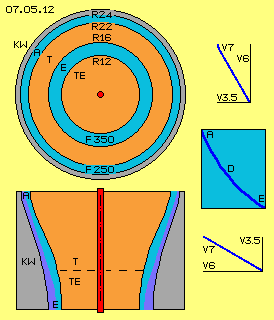 Right hand at picture, again previous curve D (dark blue) is drawn, which represents the path of water within canals. Water enters turbine downside by angle of about 30 degrees and exits turbine upside by angles of about 60 degrees. Also free-flowing water enters downside by that flat angle into inlet area, is guided into canals finally upside near outlet, i.e. exits turbine also by that steep angle.
At upside example was assumed, diagonal inlet-speed of water is about 7 m/s (V 7), i.e. by that angle of 30 degrees thus moving into horizontal direction by about 6 m/s (V 6), like turbine is moving at that level. Thus at inlet, water moves into vertical direction by about 3.5 m/s (V 3.5). If speed of 7 m/s is also assumed at outlet with that steep angle of 60 degrees, water flows into horizontal direction only by 3.5 m, however exits outlet by vertical speed of 6 m/s (see the vector-graphs).
Within pipes, speed of linear flows are inversely proportional to cross-sectional surfaces available. Here at these twist-flow movements, mass throughput in addition depends on ´gradient´ of flows resp. only speed of movement into axial direction is involved. If water exits by vertical speed of these 6 m/s through the upper opening of 250 cm^2, corresponding throughput downside at inlet with vertical speed of only 3.5 m/s would need a cross-sectional surface of about 420 cm^2. So that cross-sectional surface of only 350 cm^2 is a little too small.
Suction-Effect through Centrifugal-Force
It was mentioned above, that centripetal acceleration becomes multiple stronger than gravity acceleration already by relative slow speeds within these narrow radius. As centrifugal forces increase by square of speed, mass soon is pressing outward by multiple of its weight. With the inclination of cone-wall shown here, about one third of these forces affect parallel upward along that wall.
Water thus becomes upward shifted onto increasingly steeper path and exits outlet of turbine by rather acute angle. If now however cross-sectional surface of inlet is too narrow, not sufficient masses of water can follow into inlet resp. opposite, water is hold back by its upward movement. At least free-flowing part of water thus must move at tracks more flat, which again results increased centrifugal forces. Thus finally, an inlet with too small cross-sectional surface affects enormous suction forces and water from inlet is pulled upward vehemently.
At machines of previous chapters, turbines all times could use only flows generated by pumps. At air-drive machine it´s possible to generate areas of relative void into which air-particles fall by own drive of normal molecular movements. Autonomous acceleration up to sound-speed is possible, demanding minimum input of energy.
Water however is not compressible, i.e. pressure is transmitted immediately - however also suction has no ´clearance´ resp. acts immediately with no delay. So if here water of upper areas of machine is pushed upward by centrifugal forces, likely forces pull upward water of areas further downside. So unlike all machines described earlier, here at this machine flows are generated only based on affects of centrifugal forces. Experiments with similar machines has confirmed that more water got pulled upward than gravity was able to move down corresponding masses of water, even when just simple cones with plane surfaces were used.
Pump-Turbine-Hybrid
Turbine of previous discussed type can also work as a pump, e.g. when starting systems. If cone gets turning, surrounding water will also become rotating. At cone-wall, water gets lifted by centrifugal force. That ´pump´ has no forward-facing surfaces and so can´t affect pressure. There are only these vertical walls between ´winded staircases´. Winded ways of each ´staircase´ continuously move backward and wand water behind is dragged into turning sense of system. The higher the water is lifted, at each larger radius the water wanders outward, based on its centrifugal forces.
When turning motion is accelerated, lifting force-components become stronger and now are pressing onto diagonal surfaces of canals, so turning momentum is achieved and pump needs no longer energy-input for drive. If turning speed goes on accelerating, turbine-mode is achieved. If now no load weights onto turbine, machine will accelerate autonomously - until water can´t follow at inlet or until self-destruction of machine.
 Safety first, Exclusion of Liability
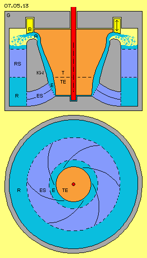
At picture 07.05.13 previous discussed elements are drawn, now embedded within housing G (grey) and added by some further elements. Most important new constructional element is ´stop-valve´ B (yellow) in shape of a ring which can be raised or lowered (see double arrow). By that valve, water masses flowing off turbine are controlled and if necessary, water-throughput completely is stopped in case of uncontrolled self-acceleration.
That ´safety-valve´ can be installed also of different construction and at other position. At any case however, construction of machines of that type at first must guarantee complete function of that constructional element. Centrifugal forces increase by square of speed, as well known, and mass of one kilogram can weight by tons onto outer wall. Parts of these enormous forces enlarge mass throughput resp. are transferred into turning momentum.
I only describe movement principles in general and why which constructional elements could be designed which kind. However, I refuse any responsibility and liability for the actual construction or use of any such machines. The complete responsibility for all risks, rests solely with whoever decides to actually construct or operate any such machines.
Circuit
As upside described in details, water (light blue) is sucked in through inlet E into area of turbine-inlet TE. Water flows upward-outward within tooth-like turbine-blades and alongside cone-wall KW. Quite upside, water is gathered within canal running all around, so at outlet A steady flat jet is redirected towards outside. This water flies into air-filled area (light yellow) and falls down by gravity (marked by blue points). Water-level of that backflow-area R is only some centimetre below outlet A. So water is to lift against gravity only that small height.
The water flows off turbine by relative steep angle, so that flow moves relative slow into turning sense of system. While flowing downward, water should turn some faster, e.g. guided by corresponding curved fins, which here are marked as ´backflow-stator´ RS (dark blue). Cone-wall is fix connected with housing by these cross-beams.
Downside at backflow-area an ´inlet-stator´ ES (dark blue) is marked and through these fins water again is guided into fitting direction. Previous described suction, generated by centrifugal forces, in general pulls water upward. However that water may not flow straight upward but must move upward spiral twisting, so again centripetal acceleration resp. centrifugal forces exist.
Space within inlet-stator e.g. is divided by six fins correspondingly curved, like schematic sketched by cross-sectional view downside of picture. These canals could additionally be divided in axial direction. By that shape (or any corresponding design) wanted rotation and gradient of flow is achieved at turbine-inlet.
Example Mazenauer and Clem
Experienced readers will be familiar with machine of Hans Mazenauer and workable engine of Richard Clem, for example by my chapter ´Auto-Motor´ of 2005 or chapter ´05.10. Tornado-Motor´ of Ether-Physics. There I mainly worked out suction-effect of twisting flow within canals, while here now at that conception of ´Centrifugal-Thrust-Engine´ enormous centrifugal forces are used.
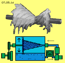 Mazenauer did use air-drive double-cones (see upside of picture 07.05.14), which did accelerate autonomously up to self-destruction. Because he got financial ruined by these experiments, Mazenauer unfortunately could not finish his work successfully. Mazenauer did use double-cone, where large part (at picture left side) did work as turbine and small part did function as pump. At a whole, air got moved within inward-turning and outward-turning vortices, overlaid by twist flows within canals.
However, a pump with that inlet from outside towards inward is not very effective. Wanted turning vortex towards turbine-inlet is better generated by stationary fins of previous inlet-stator (at least when using water as working medium).
Clem based his engine design on an asphalt-pump, and without the slightest doubt, he ran his car without consuming any common fuel. Based on known sketches and pictures, he did use a cone with canals arranged by rather small gradients (see downside at picture 07.05.14). However working-medium within such canals is ´stirred´ by that movement pattern. That´s advantageous for heating asphalt, however Clem had to cool down surplus heat of his oil used as working medium. Based on my considerations upside, canals much steeper preferably are used with much better angle for generating turning momentum. In addition, Clem´s canals were rather small and thus did show large surfaces with corresponding strong resistance.
As here centrifugal force of water is used, turning momentum is only achieved by pressure affecting on turbine surfaces. Canals thus must show only pressure-sides, onto which flows can affect at its best. So opposite to these examples of Mazenauer and Clem, based on my considerations ´canals without suction-sides´ in shape of these tooth-like turbine-blades are very advantageous.
Horizontal Shaft
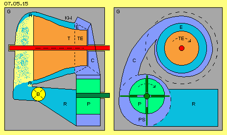 When using a horizontal shaft version of this type, some additional constructional elements and aggregates are demanded. Nevertheless that version might be an interesting alternative, e.g. like schematic sketched at picture 07.05.15. Cone-wall KW (grey) and turbine T and turbine-inlet TE (red) are analogue to previous conceptions. At outlet A however, water now falls down (see blue points) through air-filled area (light yellow) into reservoir. As in the previous example, again previous safety-valve B (yellow) is installed near outlet.
Water flows into a backflow-tank R (light blue). Form there, water is guided towards inlet E via pump P (green) and snail-conduit C. That inlet-conduit is arranged diagonal, so water flows by wanted angle into space between the turbine and the cone-wall.
Pump is installed quite downside of tank, so water is transported e.g. for starting system. At running mode, strong suction exists from the turbine and the turbine-inlet backward, so pump won´t demand much energy-input for drive but will turn just idle within that flow. At the other hand, any acceleration of pump revolutions, immediately will increase mass-throughput and thus also performance of turbine.
In principle, any pump could be used. Here for example schematic is sketched a ´slide-pump´ P with its eccentric arranged shaft and radial-moving pump-blades PS (dark green). The advantage of that kind of pump is exact volume within their chambers (at picture downside-left) which is transported each revolution. So mass-throughput is exactly controlled by pump revolutions.
Small Constructional Volumes
 This engine with horizontal shaft could be installed within vehicles to provide the mechanical drive via standard clutch and gear transmission. At the other hand, since electric energy has so many uses, this engine prevailingly could be used for drive of electric generators, e.g. also because electricity is demanded for pump and control units. That job however is also done by vertical shaft.
In general, larger constructional volume represents stronger performance. Here however, performance is based on centrifugal forces resp. centripetal acceleration and these are inverse proportional to radius. At given speed, centrifugal force at narrow radius is much stronger than at wide radius and correspondingly stronger is ´lift-component´ resp. thrust of relative small machines.
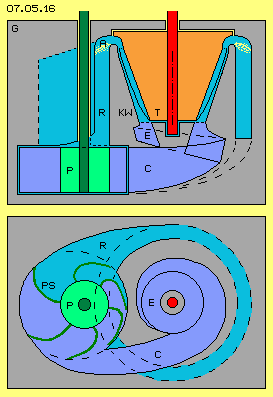
At machine sketched at picture 07.05.16, the turbine T (red) has a wide level radius of e.g. only 18 cm. the cone-wall KW (grey) reaches downward by constant angle into snail-like inlet-area (E).
Water exits turbine upside via outlet A and flows back downward within backflow-area R. This backflow is winded spiral downward and ends downside into pump P (green). Pump transports water C back into snail-like inlet below turbine. Way of water through turbine and backflow here is marked light blue, water within pump and turbine-inlet is marked dark blue.
Pump here schematic is sketches by type of impeller-pump, which shows each revolution defined throughput analogue to previous slide-pump. That engine is controlled via revolutions of pump, where resting pump practically works like stop-valve. Also here, suction from cone-wall will affect backward through inlet to pump. At running mode that pump practically will function only as ´moderator´ and won´t demand much energy-input.
It´s also possible, total inner space of machine could be filled up with water, also at area of outlet A, so closed circuit of water exists. That machine naturally could again be arranged with horizontal shaft. Above this, that general principle of movements could be realized by most different variations.
Impossible
At these consideration, naturally comes up general question on and on, why that machine could work at all. Without any question, one kilogram mass weights by tons onto inner walls of cylinder when turning fast revolutions. At cone-shaped inner walls, without any doubts that mass will press by partial forces from narrow radius towards wider radius. Without any doubt, that flow can generate mechanical turning momentum via turbine-blades as a side-effect. Which part of energy is to draw off system and which distance between turbine and cone-wall etc. will be optimum, by sure is question of experiments. It´s only sure, turbine may not take total kinetic energy off systems, because autonomous backflow-circuit must show also kinetic energy.
As water has ´cohesive consistency´, flow alongside cone-wall affects like suction onto following waters, so flow-pressure is like flow-suction and thus closed flow-circuit exists. Backflow must be organized with most less friction losses and ´force-neutral´. Decisive now is, water is guided to narrow radius of inlet, however not contrary to centrifugal forces.
Based on these conditions, steady circuit with benefit-surplus is possible. Flow-pressure of ´water-fall of heavy waters´ partly is transferred into mechanical turning momentum, afterward water must flow back on ´neutral´ way and must be guided inward to inlet-area as ´light waters´. At previous versions were mentioned diverse measurements for construction of that motion principle, following variation once more shows most advantageous solution.
Outlet and Water-Cylinder
At following picture 07.05.17 again a horizontal axis is used with that turbine T (red) inclusive its tooth-like turbine-blades TS (here also marked light red). Cone-trunk of turbine is extended by an area of turbine-inlet TE. Opposite to these surfaces, the hollow-cone of cone-wall KW (grey) is positioned, fix connected with the housing G (grey). Water (light blue) flows between these surfaces by turning movements. That arrangement of elements and movement processes correspond to previous versions.
At previous versions was suggested to integrate free-flowing part of water also into final part of turbine-canals. At the other hand, sufficient flow must exist at outlet. Only by practical experiments will be found optimum part of free-flowing water respective which part of water finally is redirected within turbine-blades. This picture for example shows design of outlet A, where all water alongside cone-wall can flow off free. Hills of blades run smoothly into bending of turbine-surface.
A new constructional element here is drawn as ring B, running all around. Water enters tangential into that ´round pipe´ and does an U-turn of about 180 degrees. Upside was assumed, water leaves outlet by angle of about 60 degrees, so water will enter that pipe by spiral track. No matter which angle, at any case water will leave that ´round half-pipe´ tangential by own centrifugal force (so here towards right side).
Sharp redirections like these, normally produce turbulent flows with corresponding strong friction losses resp. flow-resistance, e.g. within any normal pipe-bow (just because way inside is much shorter than way outside along surfaces). Here exists no inner part of such narrow bows, but water keeps turning by cylindrical movement all around. Within that water-cylinder, flow layers of different radius and different turning-speeds are balanced without friction. That pipe all around and the water rolling within works like ball-bearing, so flow off the outlet and the redirection of water towards the inlet is done by minimum losses.
Axial Backflow
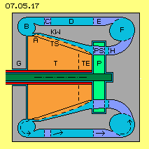 Cone-wall KW (grey) must be fix attached to outer parts of the housing G (grey) via spike-rods C (dark blue). Backflow-canal is arranged also all around, thus with ring-shaped cross-sectional surface. Water there flows still with angle of about 60 degrees. These cross-beams should be shaped like fins and should guide flow some steeper (e.g. by 75 degrees) towards right.
Cross-sectional surface of ring-shaped backflow-canal D (light blue) is relative wide, so few friction at surfaces exists. Water will move relative slow towards right within that canal. That area represents a ´buffer´ concerning throughput, because water there can move towards right by more or less twist.
Another new constructional element here are fins E (dark blue), which function like a stator. Opposite to previous versions, here flow is directed into straight axial direction (so from left to right without twist). Within backflow-canal D, water still is moving at more or less spiral track. Left end of fins E thus should be rounded, so taking these little bit turning waters without losses. Right edges of fins however should end sharp.
Opposite to few cross-beams C, about 12 to 18 cross-beams E should be installed. Cross-sectional surface of backflow-canal becomes more narrow, so flow becomes accelerated. Opposite to upside enlargement of cross-sectional surface, that narrowing does not affect resistance. By these fins E now water is guided parallel to system axis. Water there is not turning around system axis and thus does not show any centrifugal force radial outward from the system axis.
Centripetal Backflow
Analogue to previous ring B running all around outlet, here now is drawn ring F (light blue). Water enters tangential into that ring, flows radial inward towards system axis and leaves that ring via conduit H (dark blue) towards turbine. Like within ring B, also here part of water flows cylinder-like within ring F. Like upside also here that relative sharp redirection occurs without friction losses, practically like at ball-bearings.
Water moves at each radial plane, i.e. its centrifugal force all times is directed right angle onto wall. Based on that centrifugal force, water flows off ring F tangentially inward. Space within ring becomes more narrow towards inside, at the other hand opening towards conduit H offers additional space for movement. Thus water is guided inward to shorter radius of system axis and that motion is not directed against centrifugal forces (radial centripetal to system axis) but corresponds to centrifugal forces (around central axis of ring F).
Water from ring F now would run into pure axial direction towards turbine. However water must be turning around system axis, so wanted centrifugal forces alongside cone-wall come up. Therefore water must enter space between turbine and cone-wall e.g. by previous assumed flat angle of about 30 degrees at turbine-inlet. That redirection of flow (here inwards and towards right side of picture) into turning-flow (around system axis and towards right) now is done by conduit H. Fins are installed within that stator, taking water from ring F radial inward. At the following, fins are curved into turning sense of system, so water is guided by flat angle towards turbine-inlet E. These fins thus end inside by angle of previous 30 degrees showing into turning sense of system.
Pump and Control
Before water comes to area of turbine, water flows through pump P (green). Its pump-blades PS (dark blue) are arranged right angles to previous fins, so show angle of 60 degrees backward in turning sense of system. At normal mode, that pump turns ´idle´ within that diagonal flow. Suction of water at cone-wall reaches back into flow: diagonal through pump into conduit H, from there however radial into ring F and up to ring-inlet E.
So based on parts of centrifugal forces resp. these resulting thrust-forces alongside cone-wall, water is pushed off turbine-outlet A into backflow-canal D. At the other hand, based on that general flow within closed circuit, water is dragged into turbine-inlet E. As water within fins E and ring F and first part of fins H is not turning around system axis, no centrifugal forces hinder that radial inward movement. So that solution with redirection of water into radial inward-direction allows circuit by nearby null resistance.
That pump has important control-functions: normally pump turns (nearby) as fast as flow-speed there, where flow there turns likely fast as turbine at its inlet area. If stronger performance is demanded, pump is accelerated and water becomes faster rotating into turbine-inlet and immediately thus stronger thrust alongside cone-wall comes up.
Opposite, if rotation-speed of pump is reduced, water flows less flat into cone, i.e. centrifugal forces are reduced and thus also performance of turbine is diminished. If pump is totally stopped, water flows into turbine contrary to turning sense of system and thus mechanical turning momentum becomes null.
That pump thus is real ´sensitive´ instrument, serving for start of system, control of running mode, adaptation of momentary demanded performance and also for stop of system. Once more I clearly point out, that system is self-accelerating if no sufficient load weights onto turbine. It´s absolutely vital to fix maximum revolutions of turbine and to guarantee this function by adequate measurements. Once more I point out, here only theoretic considerations are presented for general design of machines, however all responsibility for any risks involved in actually producing or using any such machines resides exclusively with the people who construct of operate them.
Compact and Perfect
Machine sketched here e.g. could show these data: cylinder with outer diameter of about 60 cm and likely height. Turbine-outlet is positioned between radius 18.5 cm and 20 cm with cross-sectional surface of about 180 cm^2. If water there exits by previous 6 m/s into axial direction, mass-throughput will be about 100 kg each second (corresponding to pipe of 15 cm diameter and water flow of 100 litre each second by about 20 km/h). Pump-blades resp. turbine-inlet is positioned between radius 10 cm and 15 cm with cross-sectional surface of about 360 cm^2 and there water flows into axial direction by only previous 3.5 m/s. That throughput is achieved by a rotational rate of only 600 rpm.
Anybody can make calculations estimating the performance of that compact engine. Unlike all known machines and also all other conceptions presented here, that ´Centrifugal-Thrust-Engine´ uses these enormous centrifugal forces, not only for generating mechanical turning momentum but also for autonomously generating steady circuit of working medium.
Naturally that general design principle need to be optimised until real perfect engines are available. Probably all common combustion engines of vehicles will be replaced by that zero-consumption engine and of course, a wide range of other power requirements will also be met by this design of engine.
 Gravity- and Centrifugal-Forces
 At picture 07.05.02 previous situations at radius 24 cm and 16 cm (R 24 and R 16) once more are drawn by larger scale, now however the masses are moving at the higher rate of 6 m/s (V 6). Centripetal acceleration is corresponding stronger with A = 6^2/0.24 = about 150 m/s^2 respective A = 6^2/0.16 = about 225 m/s^2 (A 150 and A 225).
 At this picture right side once more bowling ball B is sketched, again rolling at plane towards left. Now however that ball got overlaid additional turning movement C, cross to its forward movement. Bended track D results (like any bowling-fan perfectly demonstrates).
 At this picture downside right hand, view from upside down onto that hollow cone-trunk is sketched. Track C with its rate of rise is drawn and also that steeper and shorter track D. Downside is marked by diverse curves, how water moves fan-like alongside inner wall, moving ´screw-like´ upward, however by increasing inclination.
 At picture 07.05.05 that turbine T (red) at first however simplistic is drawn as round cylinder, upside left by longitudinal view, aside by cross-sectional view and downside by view from outside (or surface opened out). At radius of 16 cm (R 16) resp. at circumference of 1 m round canals are arranged, here marked as turbine-blades TS (light blue). Here e.g. twelve of these canals are sketched, each parallel to system axis and running straight line from bottom to top.
 At picture 07.05.06 middle row, now shows jacket of that cone-trunk resp. its surface laid out flat. That track C (dark blue curve) now runs spiral upward and outward from A to B, within that sector marked blue (S 150). Since circumference at outlet is longer than at inlet (in ratio of radius 16 to 24 cm), outlet within space moves by faster absolute-speed than water moves. Thus water within canals would be accelerated (what´s not job of any turbine).
 If now water shall not move ´force-neutral´ through that cone-trunk but shall generate mechanic turning momentum, canal must be curved further backward in turning sense, like at this picture right side schematic is shown. Here for example, curve of canal is stronger bent by additional 50 degrees, like marked by curve L (dark red) which now spans sector of 90 degrees (S 90, light red, previous 40 + 50 degrees).
 Sawtooth-Blades
 Picture 07.05.09 attempts to give the impression of the spiral arrangement of previous tooth-shaped notches running around the surface of cone-trunk: at cone-like mountain are ways A (red) all around, downside beginning flat and becoming upward increasing steeper. Each way is bordered by vertical wall B (light blue), upside of which next way is arranged. Only at left hand side of mountain ways are visible, while at right hand side only these vertical walls are visible.
 Entrance of water at narrow circumference was assumed by acute angle of 30 degrees. If moving by steady angle, flow would run within a sector of about 150 degrees and exit by likely angle. Based on centrifugal forces, water however is lifted at cone-wall, takes track more steep within a sector of only about 120 degrees (S 120) and exits by angle of about 35 degrees. That path D (dark blue) is marked at jacket upside of picture several times.
 Picture 07.05.11 shows parts of area between the cone-wall KW (grey) and the turbine T (red). Free flowing water moves alongside cone-wall upward-outward. At surface of turbine, turbine-blades TS (light red) are arranged in shape of tooth-like notches. Water within these canals is guided outward by steeper track. Turning momentum is generated by redirection of these parts of water.
 Right hand at picture, again previous curve D (dark blue) is drawn, which represents the path of water within canals. Water enters turbine downside by angle of about 30 degrees and exits turbine upside by angles of about 60 degrees. Also free-flowing water enters downside by that flat angle into inlet area, is guided into canals finally upside near outlet, i.e. exits turbine also by that steep angle.
 Safety first, Exclusion of Liability
 Mazenauer did use air-drive double-cones (see upside of picture 07.05.14), which did accelerate autonomously up to self-destruction. Because he got financial ruined by these experiments, Mazenauer unfortunately could not finish his work successfully. Mazenauer did use double-cone, where large part (at picture left side) did work as turbine and small part did function as pump. At a whole, air got moved within inward-turning and outward-turning vortices, overlaid by twist flows within canals.
 When using a horizontal shaft version of this type, some additional constructional elements and aggregates are demanded. Nevertheless that version might be an interesting alternative, e.g. like schematic sketched at picture 07.05.15. Cone-wall KW (grey) and turbine T and turbine-inlet TE (red) are analogue to previous conceptions. At outlet A however, water now falls down (see blue points) through air-filled area (light yellow) into reservoir. As in the previous example, again previous safety-valve B (yellow) is installed near outlet.
 This engine with horizontal shaft could be installed within vehicles to provide the mechanical drive via standard clutch and gear transmission. At the other hand, since electric energy has so many uses, this engine prevailingly could be used for drive of electric generators, e.g. also because electricity is demanded for pump and control units. That job however is also done by vertical shaft.
 Cone-wall KW (grey) must be fix attached to outer parts of the housing G (grey) via spike-rods C (dark blue). Backflow-canal is arranged also all around, thus with ring-shaped cross-sectional surface. Water there flows still with angle of about 60 degrees. These cross-beams should be shaped like fins and should guide flow some steeper (e.g. by 75 degrees) towards right.